12 Device description
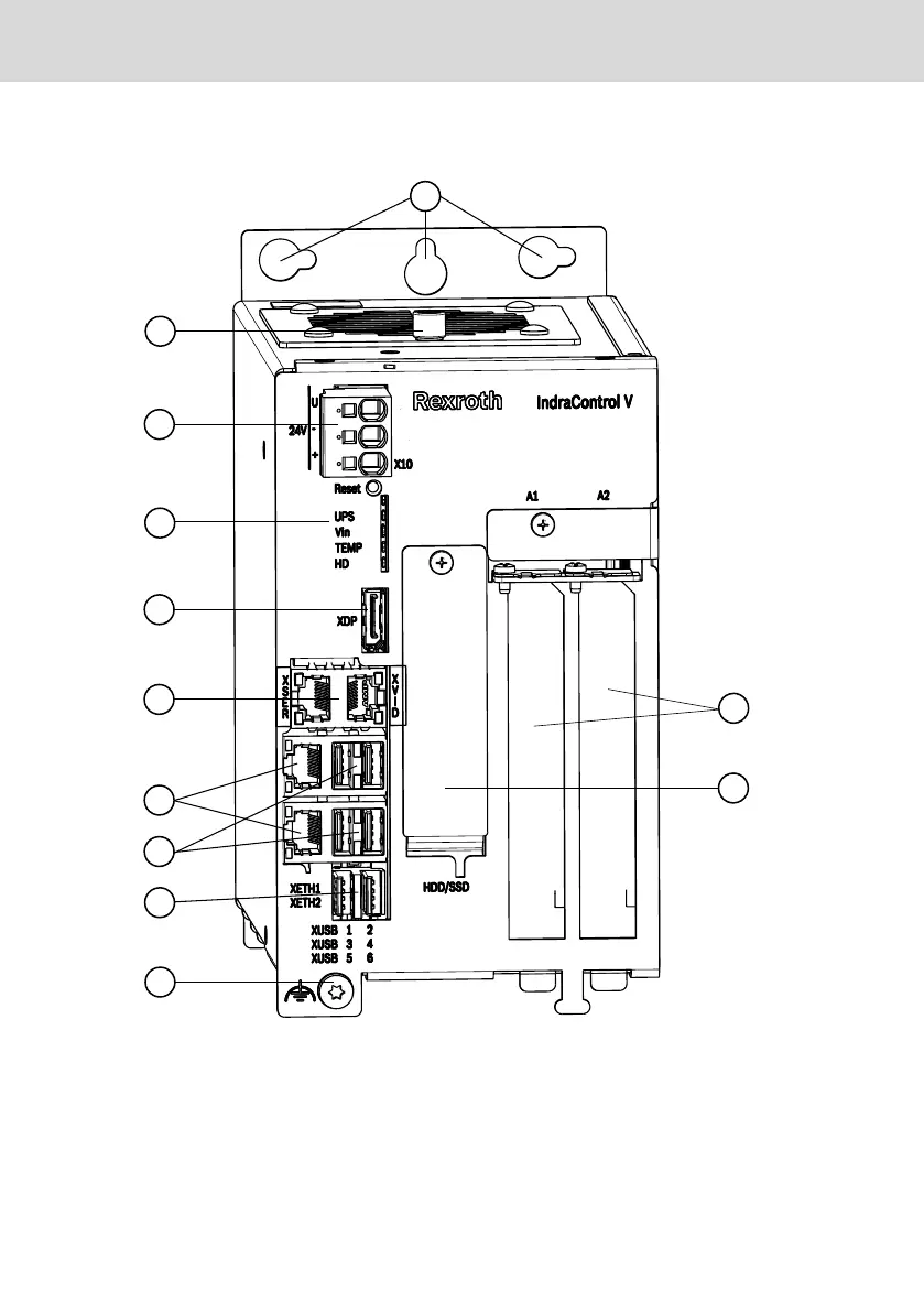
① Keyholes for mounting
② Knurled screw of the fan cover
③ Plug for voltage supply
④ Status LEDs and “Reset” button
⑤ DisplayPort
⑥ CDI+ interface (1 x RJ45) or CDI interfa-
ces (2 x RJ45)
⑦ 2 × Ethernet interfaces
⑧ 4 × USB 2.0 interfaces
⑨ 2 × USB 3.0 interfaces
⑩ Grounding screw (hexalobular T25)
⑪ Hard disk cover
⑫ 2 × slots for extension cards
Fig. 12-1: Front view of an IndraControl VPB 40.4 control cabinet PC, types L, N, P
42/57
Device description
IndraControl VPB 40.4
Bosch Rexroth AG R911376309_Edition 02

 Loading...