104
DISASSEMBLY PROCEDURES
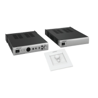
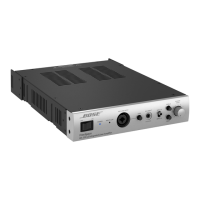
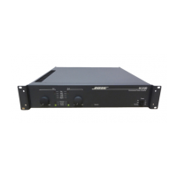
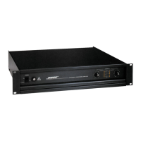
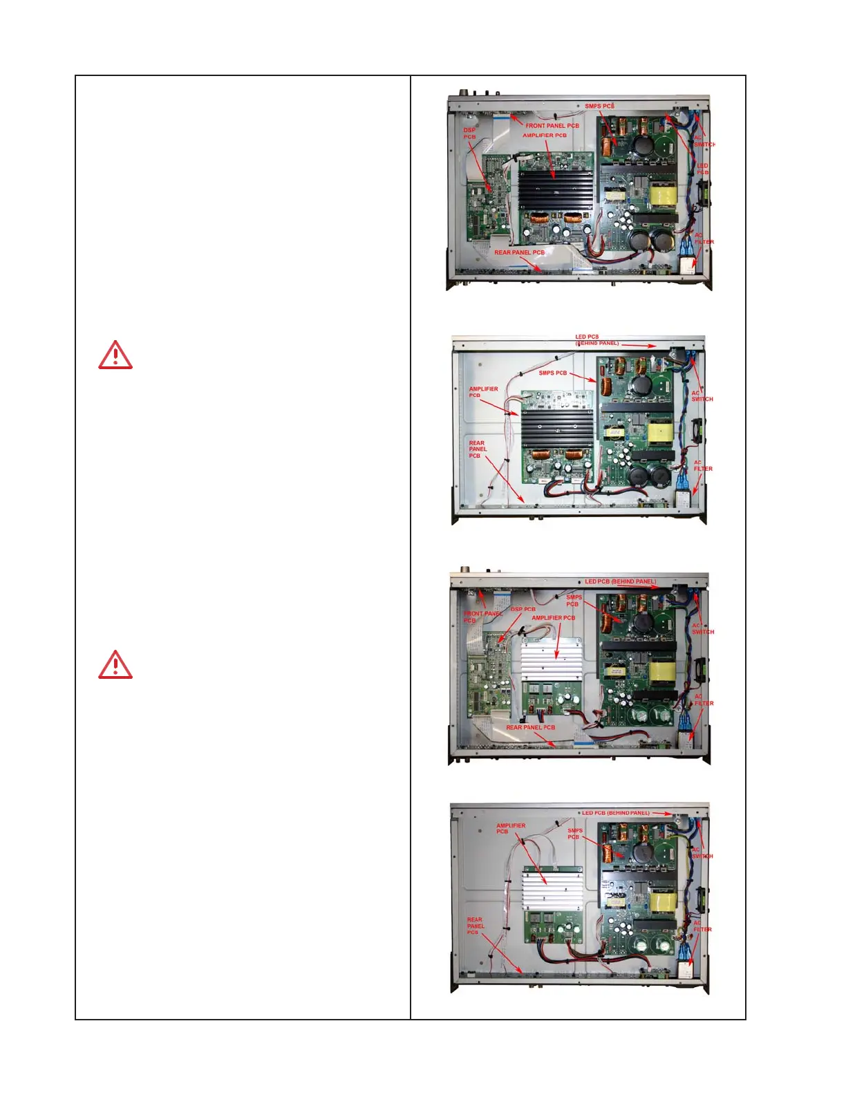
IZA 2120-HZ Chassis View
ZA 2120-HZ Chassis View
IZA 2120-LZ Chassis View
ZA 2120-LZ Chassis View
Note: The IZA 2120-HZ, IZA 2120-LZ, ZA 2120-
HZ and ZA 2120-LZ all share a similar design.
As a result, the disassembly procedures are
similar for all four models. Any differences in
disassembly are detailed in the following
procedures. Unless otherwise stated, these
procedures are common across all four
models. Refer to the chassis views at right for
board locations.
1. Top Cover Removal
1.1 Remove the 10 screws that secure the
top cover. Lift off the top cover.
CAUTION: Ensure that the insulating
sheet is properly installed on the top cover
over the SMPS PCB. This is to prevent
arcing to the top cover from the high voltage
section of the SMPS.
2. SMPS PCB Removal
2.1 Perform procedure 1.
2.2 Disconnect the wiring harnesses at J201,
J202, J203 and J204.
2.3 Remove the six screws that secure the
PCB assembly to the chassis. Lift out the
PCB assembly.
CAUTION: Ensure that the insulating
sheet is properly installed in the chassis
under the SMPS PCB. This is to prevent
arcing to the chassis from the high voltage
section of the SMPS.
3. Amplifier PCB Removal
3.1 Perform procedure 1.
3.2 Disconnect the ribbon cable at J5.
Disconnect the wiring harnesses at J1, J2
and J3.
3.3 Remove the five screws that secure the
PCB assembly to the chassis.
Note: There is one screw located in the
middle of the heatsink.
 Loading...