Design Guide - 41
CSD Properties and Operation
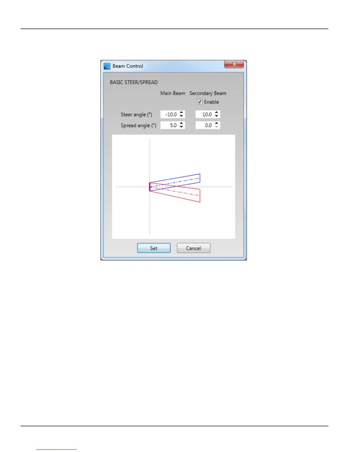
2. Beam Control window appears. Set the Steer angle and Spread angle for each beam. A red wire frame
corresponds to the Main Beam; a blue wire frame corresponds to the Secondary Beam. ‘Vocal Smoothing
Option’ is not available for this tool. Press ‘Set’ when you finish.
Note: The beam wireframes may look dierent from those in Modeler, even when the steering (and/or
spreading angle) is the same. This is because in Modeler, a user can specify the Distance (length) of the beam
lines, which does not aect the beam of this beam type. As long as the steering (spreading) angle is identical,
the radiated beam pattern is identical.
3. Now the beam pattern is transferred to the array, and you will be able to hear the change of the beam
pattern. If you like this pattern, store it to a Beam Preset (see page 35).
This function is available when either
The MSA12X device in CSD is already associated to a Physical array.
The MSA12X device in CSD has already received a beam pattern sent from Modeler.
Otherwise, the ‘Set…’ button is grayed out.
Template Files
Template files will be available on pro.Bose.com to get you started using CSD and Modeler with MSA12X.
These will include arrays for typical systems, including a 2-module Left-Right system with a single beam and
a 2-module Left-Right system with dual beams. If you are new to CSD or Modeler, it is recommended to use
these template files to start your projects.
 Loading...