690
360
450
240
460
p.
6 - Manual code:
FA01030-EN v.
1- 01/2018 - © Came S.p.A. - The manual's contents may be edited at any time without notice.
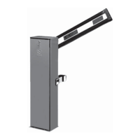
Tools and materials
Make sure you have all the tools and materials you need for installation in complete safety and in compliance with the current regulations. The
following figure shows some basic equipment needed by the installer.
INSTALLATION
⚠
The following illustrations are examples. The space for fastening the barrier and accessories varies depending on where it is installed. The
installer must find the most suitable solution.
⚠
Caution! Use hoisting equipment to transport and position the barrier.
During set-up and installation, the barrier could be unstable and tip over. Be careful and do not lean on it until it is fully fastened.
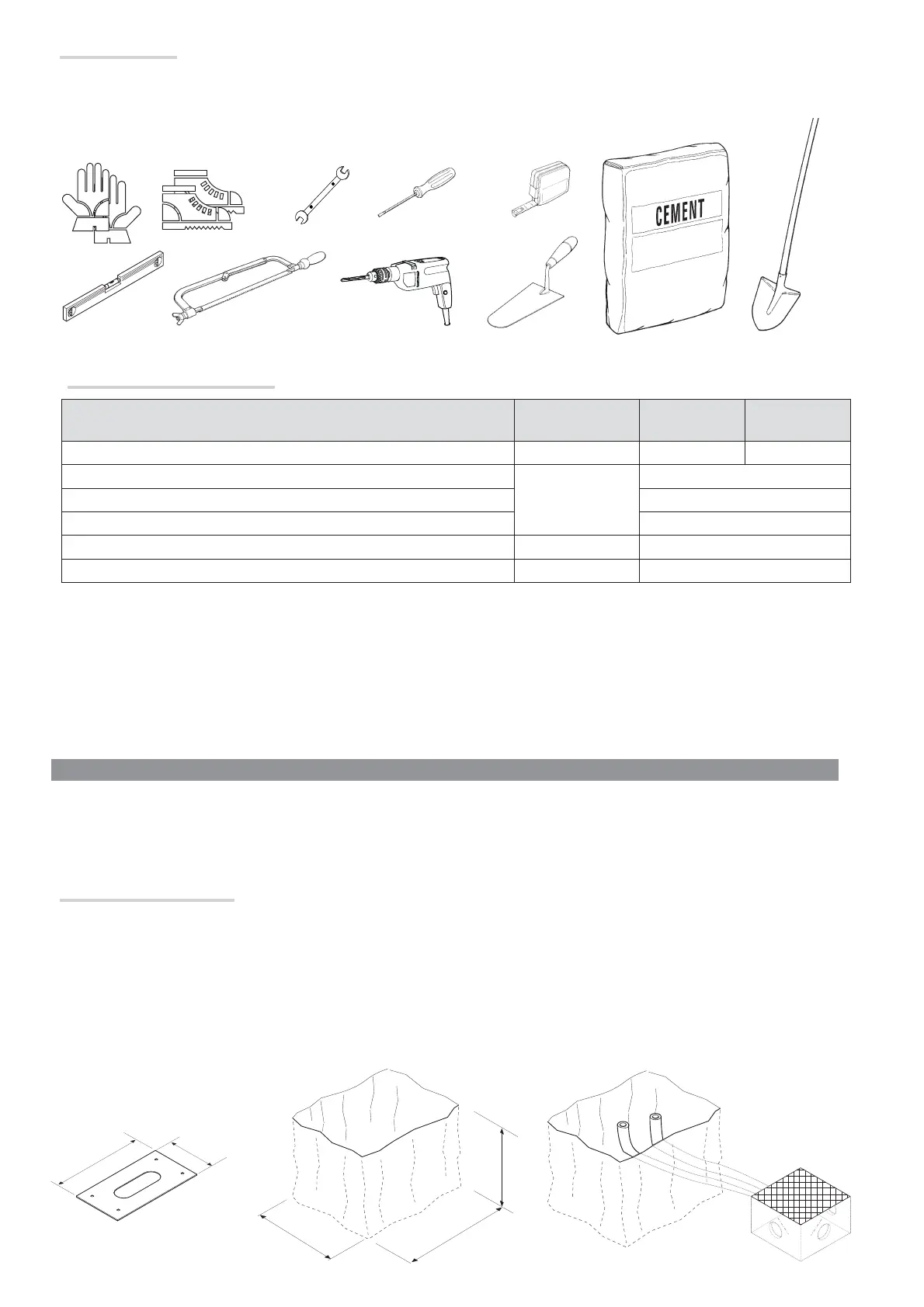
Preparing the fastening plate
⚠
If the flooring does not allow for a sturdy fastening of the entry unit, you will have to use a cement slab.
Dig a hole for the foundation frame.
Prepare the corrugated tubes you will need for the cables coming out of the junction pit.
The number of tubes depends on the type of system and the accessories you are going to fit.
Types of cable and minimum sizes
Connection Type of cable
Cable length
1 < 15 m
Cable length
15 < 30 m
Control panel power supply 230 V AC H05RN-F 3G x 1.5 mm
2
3G x 2.5 mm
2
Photocell transmitters
FROR CEI 20-22
CEI EN
50267-2-1
2 x 0.5 mm
2
Photocell receivers 4 x 0.5 mm
2
Control and safety devices 2 x 0.5 mm
2
Antenna RG58 max 10 m
Metal mass detector (see product literature)
If cable lengths di er from those specifi ed in the table, establish the cable cross-sections according to the actual power draw of the connected
devices and in compliance with regulation CEI EN 60204-1.
For multiple, sequential loads along the same line, the dimensions on the table need to be recalculated according to the actual power draw and
distances. When connecting products that are not specifi ed in this manual, please refer to the documentation provided with the products.
 Loading...