L N L1T L2T M N FC FA F + E -
10 11 E1 E6
+
-
26V
0V
230
0
24V 0
THERMAL
L N L1T L2T
p.
13 - Manual code:
FA01030-EN v.
1- 01/2018 - © Came S.p.A. - The manual's contents may be edited at any time without notice.
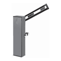
Power supply
Terminals for powering up accessories:
- 24 V AC normally;
- 24 V DC when the emergency batteries
are operating;
Overall allowed power: 40 W
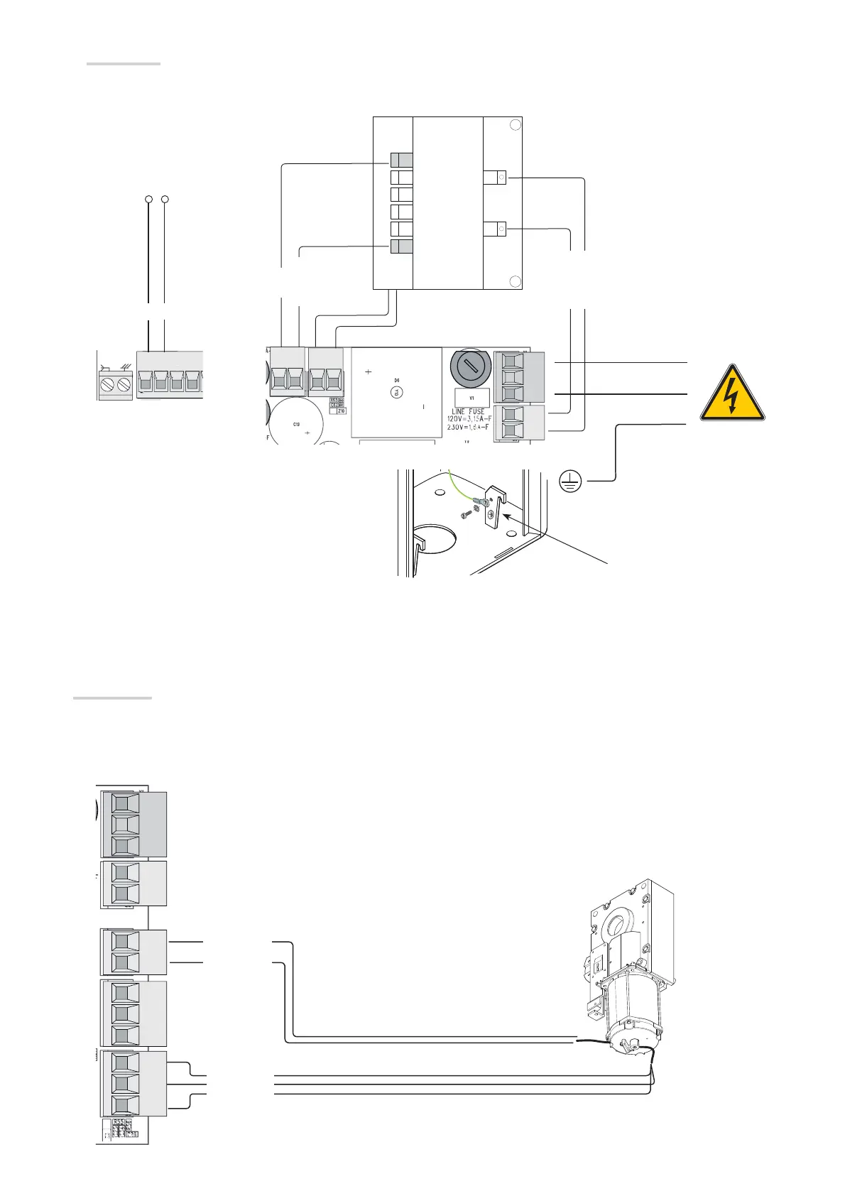
Transformer
Red
White
Blue
Orange
24 V DC gearmotor with encoder
The gearmotor is already connected.
For installations to the right of the barrier, follow the instructions in the section PREPARING THE BARRIER.
Factory wiring
White
Brown
Green
Brown
Blue
Eyelet with screw and washer for
ground connection
230 V AC, 50/60 Hz
 Loading...