ENG
14
"Carel emeter" +0300044IE rel. 1.5 - 10.11.2017
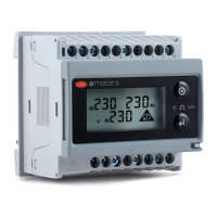
emeter3
LEDs Red LED (energy consumption),
0.001 kWh per pulse if CT ratio x VT ratio is < 7;
0.01 kWh per pulse if CT ratio x VT ratio is ≥ 7.0 < 70.0;
0.1 kWh per pulse if CT ratio x VT ratio is ≥ 70.0
< 700.0;
1 kWh per pulse if CT ratio x VT ratio is ≥ 700.0.
1000 pulse/kWh (max frequency: 16Hz) in accordance with EN 62052-11.
Maximum frequency 16 Hz, in accordance with EN 50470-3
Green LED (positioned near the terminal block) for “instrument on”, when on steady; ashing when
RS485
communication is available and operational.
Measurements See “list of the variables that can be associated:”
Method TRMS measurement of distorted waveforms.
Coupling type By external CTs.
Crest factor In 5 A: d3 (15 A max. peak).
Current overload
Continuous 6 A @ 50 Hz.
For 500 ms 120 A @ 50 Hz.
Voltage overload
Continuous 1.2 A
For 500 ms 2 A
Current input impedance
5 A < 0.3 VA
Voltage input impedance
Power supply <2 VA
Frequency 50 ± 5Hz/60 ± 5Hz.
Front keypad Two buttons for selecting the variables and programming the instrument operating parameters.
Tab. 2.a
2.2 Output specifications
Digital outputs
Number of outputs 1
Type Programmable from 0.01 to 9.99 kWh per pulse. Output can be associated with the energy meter (kWh)
Pulse duration ≥100ms < 120ms (ON), ≥120ms (OFF), in accordance with EN 62052-31.
Output Static: OPTO-MOSFET
Load VON 2.5 Vac/dc / max. 70 mA, VOFF 260 Vac/dc
max.
Insulation By opto-isolators, 4000 VRMS between output and measuring inputs.
RS485
Type Multidrop, bidirectional (static and dynamic variables).
Connection 2 wires. Maximum distance 1000 m, termination directly on the instrument.
Addresses 247, can be selected on front keypad.
Protocol MODBUS/JBUS (RTU)
Data (bidirectional)
Dynamic (read-only)
System and phase variables: see “list
of variables...”
Static (read/write) All conguration parameters.
Data format 1 start bit, 8 data bits, no parity, 1 stop bit.
Baud rate 9600 bit/s
Network devices Maximum 160 devices in the same network.
Insulation By opto-isolators, 4000 VRMS between outputs and measuring inputs.
Tab. 2.b
2.3 Software functions
Password Numerical code, max 3 digits;
Programming lock:
A trimmer located at the rear of the display module can be used to prevent block access to the instrument
conguration data.
System selection
3-Ph.n system, unbalanced load Three-phase (4 wires); three-phase (3 wires)
3-Ph.1 system, balanced load
Three-phase
(3 wires), 1 current and 3 line-to-line voltage measurements. Note: line-to-line voltage is calculated
by multiplying the virtual line-to-neutral voltage by 1.73.
Three-phase (4 wires), 1 current and 3 line-to-neutral voltage measurements. Note: line-to-line voltage is
calculated by
multiplying the virtual line-to-neutral voltage by 1.73.
Three-phase (2 wires), 1 current and 1 line-to-neutral voltage measurement (L1).
2-Ph system Two-phase (3 wires).
1-Ph system Single-phase (2 wires).
Transformer ratio
CT
from 1.0 to 99.9 / from 100 to 999 . T
he maximum output measured cannot exceed 210 MW (calculated as maximum
input current and voltage, see “Accuracy” in the previous paragraph. The maximum VT by CT ratio is 48.600)
Display
Up to 3 variables per page. See “Display pages”, 3 dierent sets of variables (see “Display pages”) according to
the
selected application
Reset Using the front keypad: total energy (kWh, kVarh)
Tab. 2.c
 Loading...