ENG
21
"Carel emeter" +0300044IE rel. 1.5 - 10.11.2017
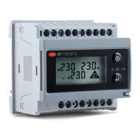
emeter3 SE
2. GENERAL CARACTERISTICS
2.1 Input specifications
Measuring inputs System: 3-phase
- Current type Not isolated (shunt inputs).
Note: the external current transformers can be earthed individually.
- Current range AV5, AV6 In: primary current corresponding to 5 A secondary output. Imax: 1.2 In (6 A secondary).
Note: “1 (6) A” capacity is available but does not comply with EN 50470-3
- Current
range MV5, MV6 In: primary current corresponding to 0.333 V secondary output. Imax: 1.2 In (0.4 V secondary).
- Voltage (direct or via VT) AV5, MV5: 230/400VLL; 6 A; A: from 160 to 260VLN (from 277 to 450 VLL).
AV6, MV6: 120/230VLL; 6 A; A: from 40 to 144VLN (from 70 to 250 VLL).
Accuracy (Display + RS485)
(@25°C ±5°C, RH 60%, 50 Hz)
In: see below, A: see below
- Current models AV5, AV6 from 0.002 In to 0.2 In: ±(0.5% RDG +3DGT). From 0.2 In to Imax: ±(0.5% RDG +1DGT).
- Current models MV5, MV6 from 0.002 In to 0.2 In: ±(1% RDG +3DGT).
From 0.2In a Imax: ±(0.5% RDG +1DGT).
- Phase-neutral voltage In the range Un: ±(0.5% RDG +1DGT)
- Phase-phase voltage In the range Un: ±(1% RDG +1DGT)
- Frequency
range: from 45 to 65Hz; resolution: ±1Hz
- Active power
±(1%RDG +2DGT).
- Power factor
±[0,001+1%(1,000 - “PF RDG”)]
.
- Reactive power
±(2%RDG +2DGT).
- Active energy
class B in accordance with EN 50470-1-3;
class 1 in accordance with EN 62053-21.
- Reactive energy class 2 in accordance with EN 62053-23.
Start-up current: 10mA.
Additional errors
- Inuence quantities
In accordance with EN62053-21, EN50470-1-3, EN62053-23
- Temperature drift
≤200ppm/°C.
- Sampling rate
1600 samples/s @ 50Hz, 1900 samples/s @ 60Hz
Display refresh time 1 second
Display 2 lines
1st line: 7-DGT or 3-DGT + 3-DGT
2nd line: 3-DGT or 3-DGT
- Type
LCD, h 7mm.
- Instant variable readings
3-DGT.
- Energy
Total imported 5+2, 6+1 or 7DGT
-
Overload for instant values EEE displayed when the value being measured exceeds the “continuous input overload” (maximum measurement
capacity).
- Max. and min. indications Max. instant variables: 999; energy: 9 999 999.
Min. instant variables: 0; energy 0,00.
Red LED (Energy consumption)
AV5, AV6 0.001 kWh per pulse if CT ratio x VT ratio is
< 7; 0.01 kWh per pulse if CT ratio x VT ratio is ≥ 7.0 and < 70.0; 0.1 kWh
per pulse if CT ratio x VT ratio is ≥ 70.0 and < 700.0; 1 kWh per pulse if CT ratio x VT ratio is
≥ 700.0.
MV5, MV6 0.001 kWh per pulse if TV / In ratio is < 35; 0.01 kWh per pulse if TV / In ratio is ≥ 35.0 and < 70.0; 0.1 kWh per pulse
if TV / In ratio is ≥ 350.0 and
< 3500.0; 1 kWh per pulse if CT ratio x VT ratio is ≥ 700.0.
- Maximum frequency 16Hz, in accordance with EN50470- 3. Green LED (positioned near the terminal block) for “instrument on”, when on
steady; ashing when RS485 communication is available and operational.
Measurements
See “list of the variables
that can be associated:”
- Method
TRMS measurement of distorted waveforms.
- Coupling type By external TA.
Crest factor AV5, AV6: ≤3 (15 A peak max.). MV5, MV6: 1.414 @ Imax (Imax=1.2 In = 0.4V). In any case: Vpeak max = 0.565 V.
Current overload
- Continuous
1.2 In, @ 50 Hz
- For
500 ms
20 In, @ 50 Hz
Voltage overload
- Continuous
1.2 Un
- For 500 ms
2 Un
Current input impedance
- AV5, AV6
- MV5, MV6
< 0,3VA
>100 k
Voltage input impedance
- Power supply < 2VA
Frequency 50 ± 5Hz/60 ± 5Hz.
Front keypad Two buttons for selecting the variables and programming the instrument operating parameters.
Tab. 2.a
 Loading...