11
Step 5 — Field Fabricate Ductwork
Cabinet return-air static pressure (a negative condition)
shall not exceed 0. 35 in. wg (87 Pa) with economizer or
0.45 in. wg (112 Pa) without economizer.
For vertical ducted applications, secure all ducts to roof curb
and building stru ctur e. Do not connect ductwork to unit.
Fabrica te supply ductwork so that the cross sectional
dimensions are equal to or greater than the unit supply
duct opening dimensions for the first 18 in. (458 mm) of
duct length from the unit basepan.
Insulate and weatherproof all external ductwork, joints,
and roof openings with counter flashing and mastic in
accordance with applicable codes.
Ducts passing through unconditioned spaces must be
insulated and covered with a vapor ba rrier.
If a plenum return is used on a vertical unit, the return
should be ducted through the roof deck t o comply with
applicable fire codes.
PROPER TY DAMAGE HAZARD
Failure to follow this caution may result in damage
to roofing materials.
Membrane roofs can be cut by sharp sheet metal
edges. Be careful when placing any sheet metal parts
on such roof.
CAUTION
!
For Units with Accessory Electric Heaters —
All installations require a minimum clearance to
combustible surfaces of 1 --in (25 mm) from duct for first
12--in (305 mm) away from unit.
Outlet grilles must not lie directly below unit discharge.
PERSONAL INJURY HAZARD
Failure to follow this warning could cause personal
injury.
For vertica l supply a nd return units, tools or parts
could drop into ductwork and cause an injury. Install
a 90--degree turn in the return ductwork between the
unit and the conditioned space. If a 90--degree e lbow
cannot be installed, then a grille of sufficient strength
and density should be installed to prevent objects
from falling into the conditioned space. Due to
electric heater, supply duc t will require 90--degree
elbow.
!
WARNING
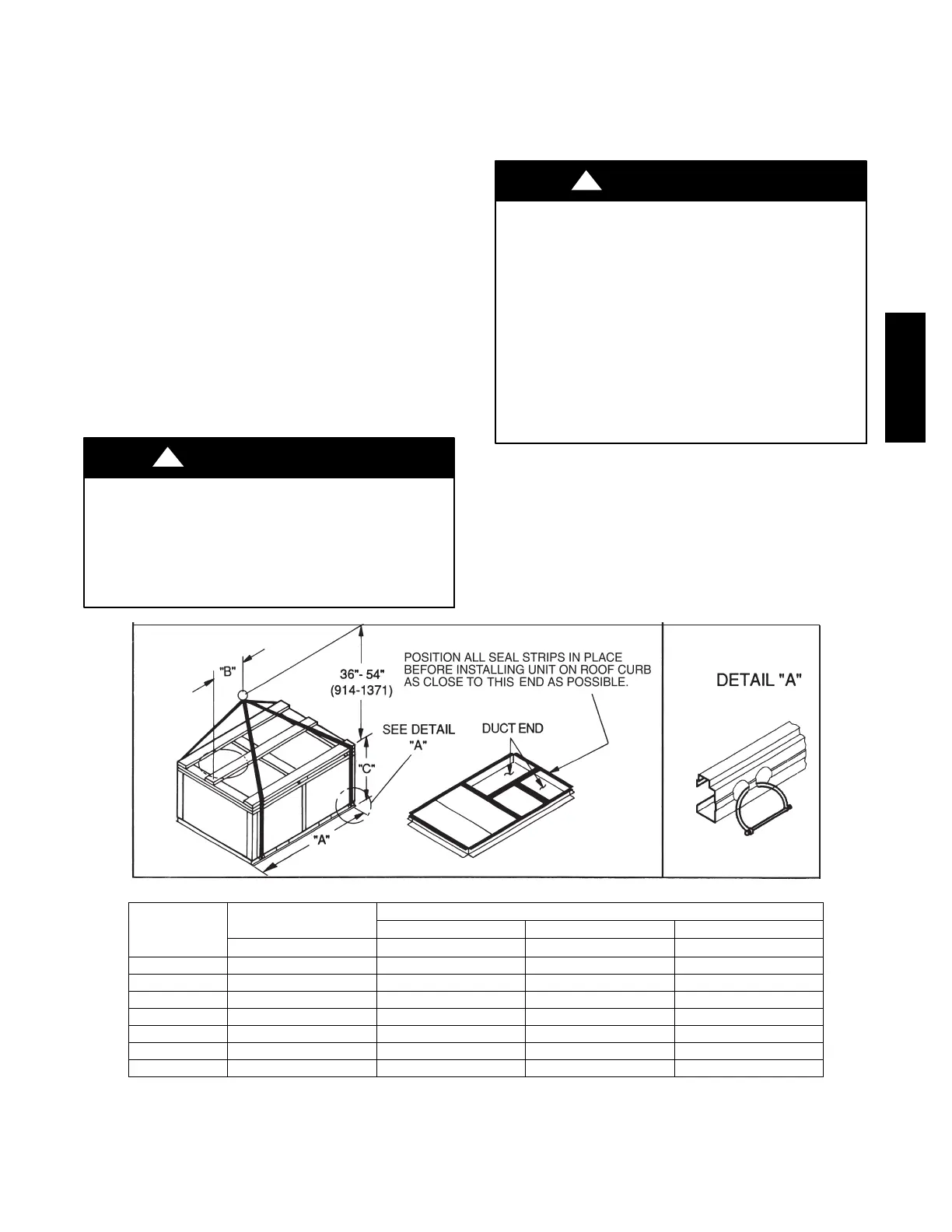
C06005
UNIT
MAX WEIGHT
DIMENSIONS
A B C
LB KG IN MM IN MM IN MM
50TC ---A08 1290 586 88.0 2235 40.0 1015 41.5 1055
50TC ---A09 1410 641 88.0 2235 39.5 1005 49.5 1255
50TC ---A12 1515 689 88.0 2235 41.0 1040 49.5 1255
50TC ---D/E08 1410 641 88.0 2235 41.0 1040 41.5 1055
50TC ---D/E09 1525 693 88.0 2235 40.5 1030 49.5 1255
50TC ---D/E12 1565 711 88.0 2235 40.0 1015 49.5 1255
50TC ---D/E14 1720 782 88.0 2235 28.5 725 53.0 1345
NOTES:
1. Dimensions in ( ) are in millimeters.
2. SPREADER BARS REQUIRED — Top damage will occur if spreader bars are not used.
3. Hook rigging shackles through holes in base rail, as shown in detail “A.” Holes in base rails are centered around the unit center of gravity .
Use wooden top to prevent rigging straps from damaging unit.
Fig. 7 -- Rigging Details
50TC

 Loading...


