8
C
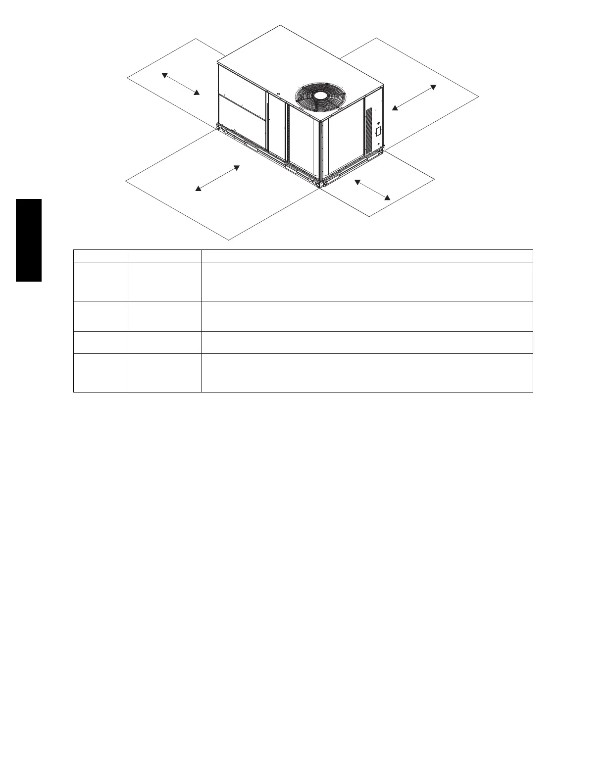
B
A
D
C08337
LOCATION DIMENSION CONDITION
A
48---in (1219 mm)
18---in (457 mm)
18---in (457) mm
12---in (305 mm)
Unit disconnect is mounted on panel
No disconnect, convenience outlet option
Recommended service clearance
Minimu m clearance
B
42---in (1067 mm)
36---in (914 mm)
Special
Surface behind servicer is grounded (e.g., metal, masonry wall)
Surface behind servicer is electrically non ---conductive (e.g., wood, fiberglass)
Check sources of flue products within 10---ft of unit fresh air intake hood
C
36---in (914 mm)
18---in (457 mm)
Side condensate drain is used
Minimu m clearance
D
48---in (1219 mm)
42---in (1067 mm)
36---in (914 mm)
Special
No flue discharge accessory installed, surface is combustible material
Surface behind servicer is grounded (e.g., metal, masonry wall, another unit)
Surface behind servicer is electrically non ---conductive (e.g., wood, fiberglass)
Chec k for adjac ent units or building fresh air int ak e s within 10---ft (3 m) of this uni t’s flue out let
NOTE: Unit not designed to have overhead obstruction. Contact Application Engineering for guidance on any application
planning overhead obstruction or for vertical clearances.
Fig. 4 -- Service Clearance Dimensional Drawing
INSTALLATION
Jobsite Survey
Complete the following checks before installation.
1. Consult local building codes a nd the NEC (National
Electrical Code) ANSI/NFPA 70 for special installa-
tion requirements.
2. Determine unit l ocation (from project plans) or select
unit location.
3. Check for possible overhead obstructions which may
interfere with unit lifting or rigging.
Step 1 — Plan for Unit Location
Select a location f or the unit and its support system (curb
or other) that provides for the minimum clearances
required for safet y. This includes the clearance to
combustible surfaces, unit performance and service access
below, around and above unit as specified in unit
drawings. See Fig. 4.
NOTE: Consider also the effect of adjacent units.
Unit may be installed directly on wood floo rin g or on Clas s
A, B, or C roof--covering material when roof curb is used.
Do not install unit in a n indoor location. Do not locate air
inlets near exhaust vents or other sources of conta minated
air.
Although unit is weatherproof, avoid locations that permit
water from higher level runoff and overhangs to fall onto
the unit.
Select a unit mounting system that provides adequate height
to allow installation of condensate trap per requirements.
RefertoStep9—InstallExternalCondensate T rap and
Line – for required trap dimensions.
Roof mount —
Check building codes for weight distribution
requirements. Unit ope rating weight is shown in Table 1.
Step 2 — Plan for Sequence of Unit Installation
The support method used for this unit will dictate different
sequence s for the steps of unit installation. For example,
on curb--mounted units, some accessories must be
installed on the unit before the unit is placed on the curb.
Revie w the following for recommended sequences for
installation steps.
50TC

 Loading...


