14
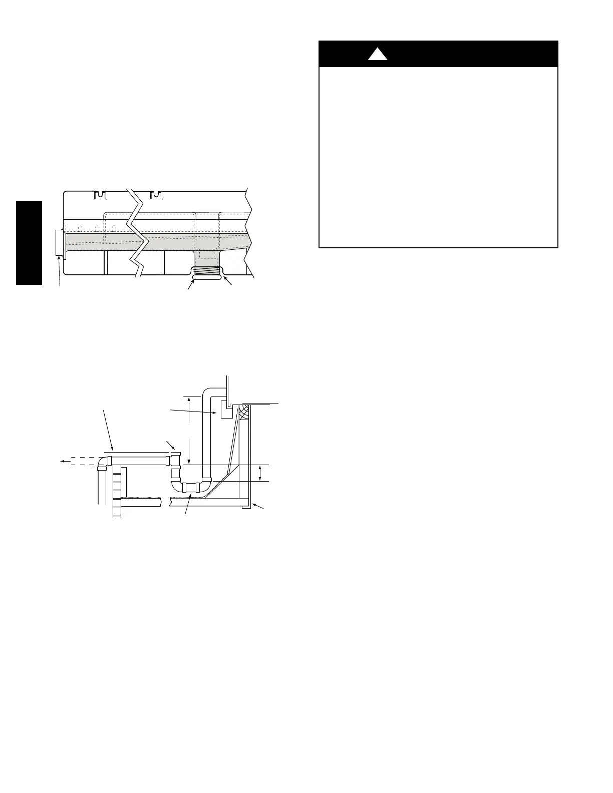
Step 9 — Install External Condensate Trap and
Line
The unit has one
3
/
4
-in. condensate drain connection on
the end of the condensate pan and an alternate connection
on the bottom. See Fig. 14. Unit airflow configuration
does not dete rmine which drain connection to use . Either
drain connection can be used with vertical or horizontal
applications.
To use the alternate bottom drain connection, remove the
red drain plug from the bottom connection (use a
1
/
2
-- i n .
square socket drive extension) and install it in the side
drain connection.
DRAIN
(FACTORY-INSTALLED)
PLUG
CONDENSATE PAN (SIDE VIEW)
STANDARD
SIDE DRAIN
ALTERNATE
BOTTOM DRAIN
C08021
Fig. 14 -- Condensate Drain Pan (Side View)
The piping for the condensate drain and e xternal trap can
be completed after the unit is in place. See Fig. 15.
NOTE: Trap should be deep enough to offset maximum unit static
difference. A 4” (102mm) trap is recommended.
MINIMUM PITCH
1” (25mm) PER
10’ (3m) OF LINE
BASE RAIL
OPEN
VENT
TO ROOF
DRAIN
DRAIN PLUG
ROOF
CURB
SEE NOTE
3˝ (76mm)
MIN
C11291
Fig. 15 -- Condensate Drain Piping Details
All units must have an external trap for condensate
drainage. Install a trap at least 4-in. (102 mm) deep and
protect against freeze-up. If drain line is installed
downstream from the external trap, pitch the line away fr om
the unit at 1-in. per 10 ft (25 mm in 3 m) of run. Do not use
a pipe size sma ller than the unit connection (
3
/
4
-in.).
Step 10 — Make Electrical Connections
ELECTRICAL SHOCK HAZARD
Failure to follow this warning could result i n personal
injury or death.
Do not use gas piping as an elec trical ground. Unit
cabi net must have an uninterrupted, unbroken
electrical ground to minimize the possibility of
personal injury if an electrica l fault should oc cur. This
ground may consist of electrical wire connected t o
unit ground lug in control compartment, or conduit
approved for e lectrical ground when install ed in
accordance with NEC (National Electrical Code);
ANSI/NFPA 70, latest edition (in Canada, Canadian
Electrical Code CSA [Canadian Standards
Association] C22.1), and local electrical codes.
!
WARNING
NOTE: Check all factory and field electrical connections
for tightness. Field--supplied wiring shall conform with
the limitations of 63_F(33_C) rise.
Field Power Supply —
If equipped with opti onal Powered Conve nience Outlet:
The power source leads to the convenience outlet’s
transformer pri mary are not factory connected. Installer
must connect these leads according to required operation
of the convenience outlet. If an always--energized
conveni ence outlet operation is desired, connect the
source lea ds to the l ine side of the unit--mounted
disconnec t. (Check with local codes to ensure this method
is acceptable in your area.) If a de--energize via unit
disconnec t switch operation of the convenience outlet is
desired, connect the source leads to the load side of the
unit disconne ct. On a unit without a unit--mounted
disconnec t, connect the source leads t o compressor
contactor C and indoor fan contactor IFC pressure lugs
with unit field power leads.
All units except 208/ 230-v units are factory wired for the
voltage shown on the nameplate. If the 208/230-v unit is
to be connected to a 208-v power supply, the control
transformer must be rewired by moving t he black wire
with the
1
/
4
-in. female spade connector from the 230--v
connec tion and moving it to the 208-v
1
/
4
-in. male
terminal on the primary side of the transformer. Refer to
unit label diagram for additional information. Fiel d power
wires will be connected line--side pressure lugs on the
power t erminal block or at fact ory--install ed option
non--fused disconnect.
Field power wires are connected to the unit at line-- side
pressure lugs on c ompressor contactor C and indoor fan
contactor IFC (see wiring diagram label for control box
component arrangeme nt) or at fac tory--installed option
non--fused disconnect switch. Max wire size is #4 AWG
(copper only).
50TC

 Loading...


