43
Return Air Enthalpy Sensor —
Mount the return--air enthalpy sensor (33CSENTSEN) in
the return--air section of the economizer. The return air
sensor is wired to the enthalpy controller
(33CSENTHSW). See Fig. 73.
GRA
BLK
RED
– 4-20
Main
+ VDC
Out
– 4-20 Main
Out
+ 24-36
VDC In
LOW
GND
24V
7
PL6-1 (24-V)
PL6-4 (COM)
Outside Air
Enthalpy Switch
Return Air
Enthalpy
Sensor
CTB ECON
(P’LINK: to J4-2) or
(RTU Open: to J2-6)
C11161
Fig. 73 -- Outside and Return Air Enthalpy Sensor
Wiring
Smoke Detectors
Smoke detectors are available as factory--installed options on
50TC models. Smoke detectors may be specified for Supply
Air only or for Return Air without or with economizer or in
combination of Supply Air and Return Air . All components
necessary for operation are factory--provided and mounted.
The unit is factory--conf igu red for immediate smoke detector
shutdown operation; additional wiring or modifications to
unit terminal board may be necessar y to complete the unit
and smoke detector configuration to meet project
requirements.
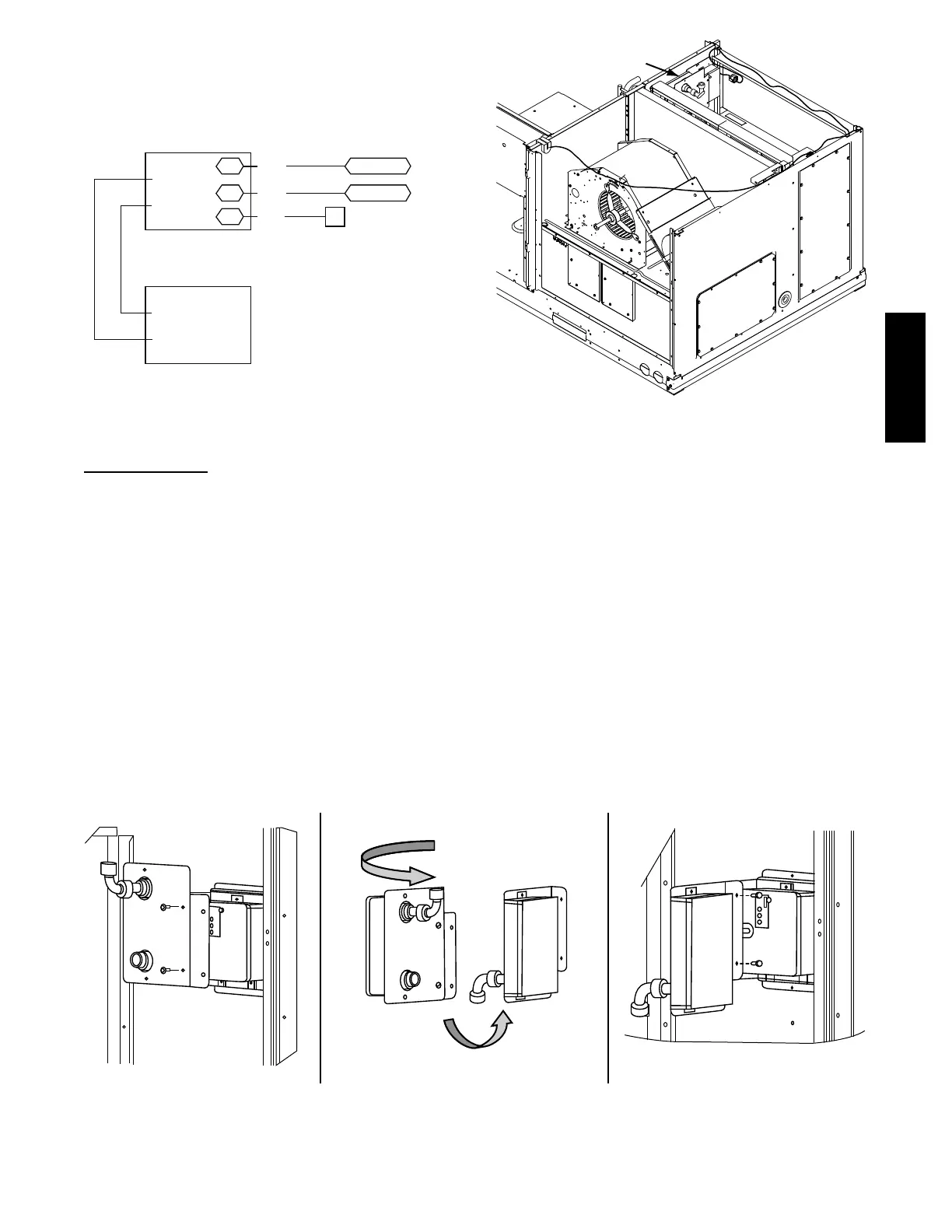
Units equipped with factory--optional Return Air smoke
detectors require a relocation of the sensor module at unit
installation. See Fig. 74 for the as shipped location.
Return Air
Smoke Detector
(as shipped)
C12282
Fig. 74 -- Return Air Smoke Detector, Shipping Position
Completing Installation of Return Air Smoke Sensor:
1. Unscrew the two screws holding the Return Air
Smoke Detec tor assembly. See Fig. 75, Step 1. Save
the screws.
2. Turn t he assembly 90 degrees and then rotate end to
end. Make sure that the elbow fitting is pointing
down. See Fig. 75, Step 2.
3. Screw the sensor and detector plate into its operating
pos itio n using screw s from Step 1. See Fig. 75, Step 3.
4. Connect the flexible tube on the sampling inlet to the
sampling tube on the basepan.
Additional Application Data —
Refer to the Application Data sheet titled Factory
Installed Smoke Detectors for Small and Medium Rooftop
Units2to25Tonsfor discussions on additional control
features of these smoke detectors including multiple unit
coordina tion.
Step 1 Step 2 Step 3
C12283
Fig. 75 -- Completing Installation of Return Air Smoke Sensor
50TC

 Loading...


