12
Step 6 — Rig and Place Unit
Keep unit upright and do not drop. Spreader bars are not
requir ed if top crating is left on unit. Roller s may be used to
move unit across a roof. Level by using unit frame as a
reference. See Table 1 and Fig. 7 for additional information.
Lifting hole s are provi ded in base rails as shown in Fig. 7.
Refer to riggi ng instructions on unit.
Rigging materials under unit (cardboard or wood) must be
removed PRIOR to placing t he unit on the roof curb.
When using the standard side drai n connection, ensure the
red plug in the alternate bottom connection is tight. Do
this before setting the unit in place. The red drain pan can
be tightened with a
1
/
2
--in. square socket drive extension.
For further details see Step 9 -- Install External
Condensate Trap and Line on page 14.
Before setting the unit onto the curb, recheck gasketing on
curb.
UNIT DAMAGE HAZARD
Failure to follow this caution may result in
equipment damage.
All panels must be in place when riggi ng. Unit is not
designed for handling by fork truck.
CAUTION
!
PositioningonCurb—
Position unit on roof curb so that the following
clearances are maintained:
1
/
4
in. (6.4 mm) clearance
betwee n the roof c urb and the base rai l i nside the front
and back, 0.0 in. clearance between the roof curb and
the base rail inside on the duct end of the unit. This will
result in the distance between the roof curb and the base
rail i nside on the c ondenser end of t he unit being
approximately
1
/
4
in. (6.4 mm).
Although unit is wea therproof, guard against water from
higher level runoff and overhangs.
After unit is in position, remove rigging skids and
shipping materials.
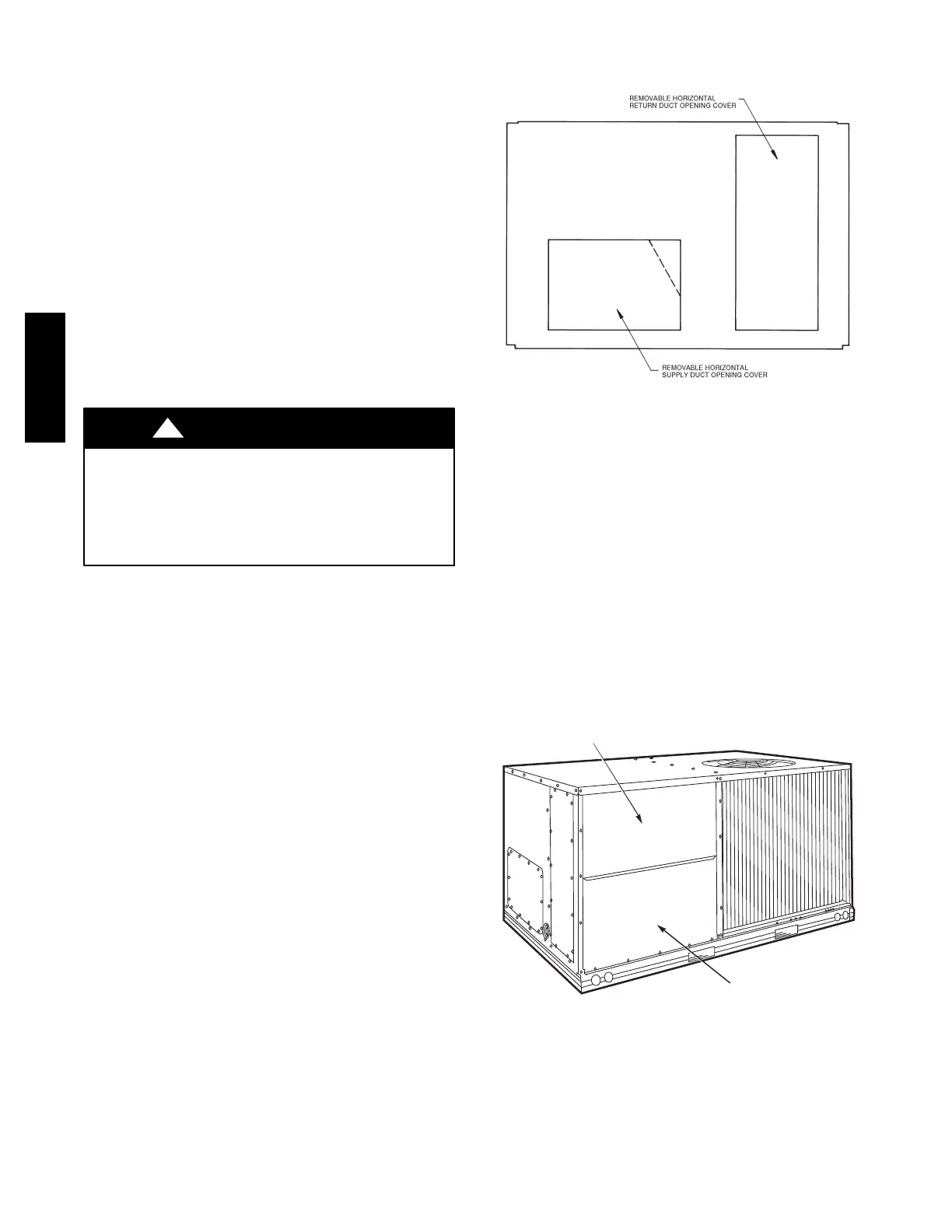
Step 7 — Convert to Horizontal and Connect
Ductwork (when required)
Unit is shipped in the vertical duct configuration. Unit
without factory--installed economizer or return air smoke
detector option may be field--converted to horizontal ducted
configuration. To convert to horizontal configuration,
remove screws from side duct opening covers and remove
covers. Using the same screws, install covers on vertical
duct openings with the insulation--side down. Seals around
duct openings must be tight. See Fig. 8.
Field--supplied flanges should be attac hed to horizontal
duct openings and al l ductwork should be secured to the
flanges. Insulate and weatherproof all external ductwork,
joints, and roof or buil ding openings with count er flashing
and mastic in accordance with applicable codes.
Do not cover or obscure visibility to the unit’s informative
data plate when insulati ng horizontal ductwork.
C06108
Fig. 8 -- Horizontal Conversion Panels
Step 8 — Install Outside Air Hood
Economizer and Two Position Damper Hood
Package Removal and Setup -- Factory Option
1. The hood is shipped in knock--down form and must be
field assembled. The indoor coil access panel is used as
the hood top while the hood sides, divider and filter are
packaged together, attached to a metal support tray us-
ing plastic stretch wrap, and shipped in the return air
compartment behind the indoor coil access panel. The
hood assembly’ s metal tray is attached to the basepan
and also attached to the damper usin g two plastic tie--
wraps.
2. To gain access to the hood, remove the filter access
panel. (See Fig. 9.)
FILTER ACCESS PANEL
INDOOR COIL ACCESS PANEL
C10146
Fig. 9 -- Typical Access Panel Locations
3. Locate the (2) screws holding the metal tray to the
basepan and rem ove. Locate and cut the (2) plastic
tie--wraps securing the assembly to the damper. (See
Fig. 10.) Be careful to not damage any wiring or cut
tie--wraps securing any wiring.
50TC

 Loading...


