16
Units Without Factory--Installed
Non-- Fused Disconnect —
When installing units, provide a disconnect switch per
NEC (National Electrical Code) of adequate size.
Disconnect sizing data is provided on the unit informative
plate. Locate on unit cabinet or within sight of the unit per
national or loc al codes. Do not cover unit informative
plate if mounti ng the disconnect on t he unit cabinet.
All Units —
All field wiring must comply with NEC and all local
codes. Size wire based on MCA (Minimum Circuit Amps)
on the unit informative plate. See Fig. 19 for power wiring
connec tions to the unit power terminal block and
equipment ground. Maximum wire size is #4 ga AWG per
pole.
C IFC
Disconnect factory test leads
and discard.
13 13
L1
L2 L3
208/230-3-60
460-3-60
575-3-60
Units Without Disconnect Option
Units With Disconnect Option
13 5
24 6
L1 L2 L3
Factory
Wiring
Disconnect
per
NEC
Optional
Disconnect
Switch
11
C09349
Fig. 19 -- Power Wiring Connections
Provide a ground--fault and short--circuit over--current
protection device (fuse or breaker) per NEC Article 440
(or local codes). Re fer to unit informative data plate for
MOCP (Maximum Over--current Protection) device size.
All units except 208/230-v units are factory wired for the
voltage shown on the nameplate. If the 208/230-v unit is to
be connected to a 208-v power supply, the control
transformer must be r ewired by moving the black wire with
the
1
/
4
-in. female spade connector from the 230--v
connection and moving it to the 208-v
1
/
4
-in. male termin al
on the primary side of the transform er. Ref er to unit label
diagram for additional information.
Voltage to compressor terminals during operation must be
within voltage range i ndicated on unit nameplate. On
3--phase units, volta ges between phases m ust be balanced
within 2% and the current within 10%. Use the formula
shown in the legend for Tables 10 and 11, Note 3 (see
page 55) to determine the perc ent of voltage imbala nce.
Operati on on improper line voltage or excessive phase
imbalance constitutes abuse and may cause damage to
electrical components. Such ope ration would invalidate
any applicable Carrier warranty.
NOTE: Check all factory and field electrical connections
for tightness.
Convenience Outlets —
ELECTRICAL OPERATION HAZARD
Failure to follow this warning could result i n personal
injury or death.
Units with convenience outlet circuits may use
multiple disconnects. Check convenience outlet for
power status before opening unit for servic e. Locate
its disconnect switch, if a ppropriate, and open it.
Tag--out this switch, if necessary.
!
WARNING
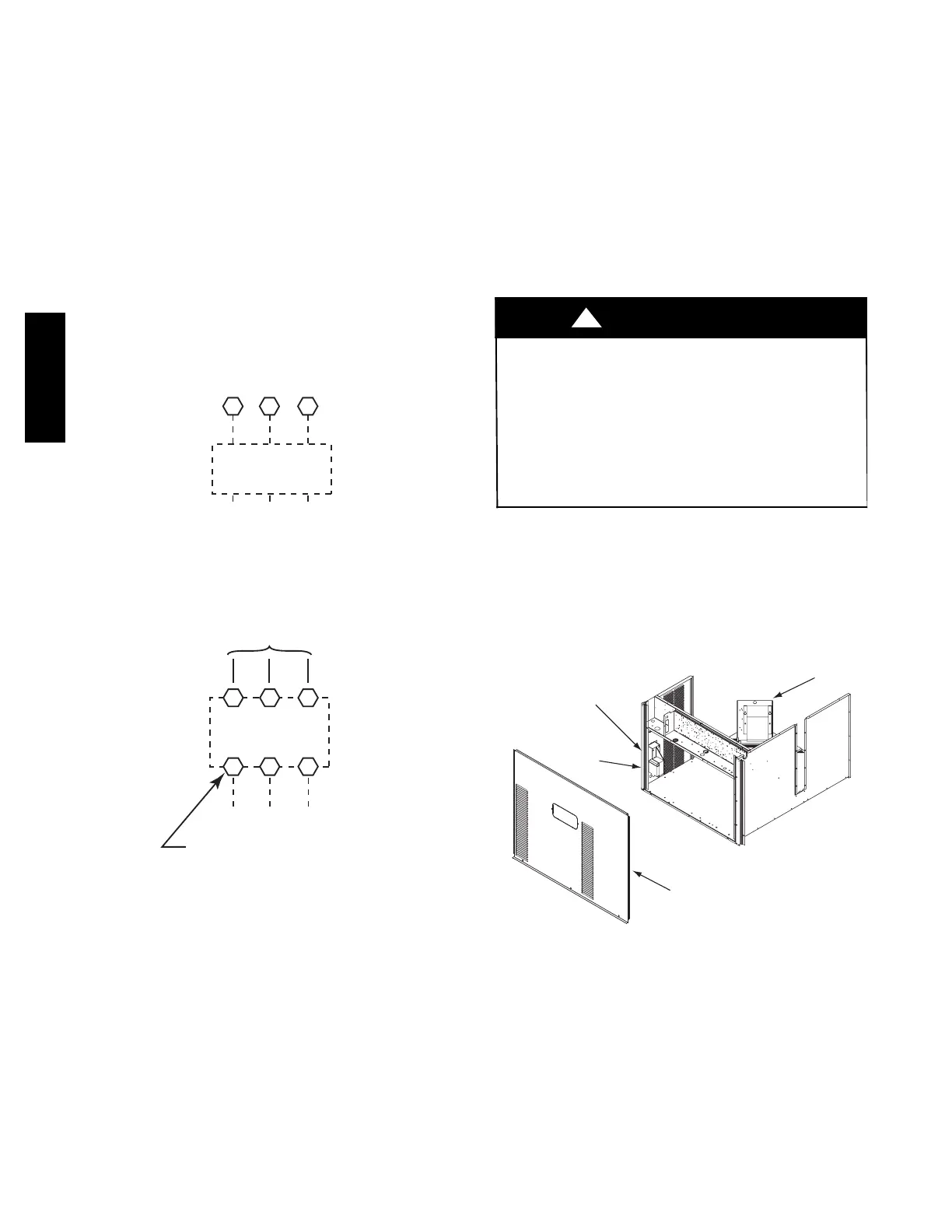
Two types of convenience outlets are of fered on 50TC
models: Non--powered and unit--powered. Both types
provide a 125--volt GFCI (ground--fault circuit--interrupter)
duplex receptacle rated at 15--A behind a hinged waterproof
access cover, located on the end panel of the unit. See Fig.
20.
Convenience
Outlet
GFCI
Pwd-CO
Fuse
Switch
Pwd-CO
Transformer
Control Box
Access Panel
C08128
Fig. 20 -- Convenience Outlet Location
Installing Weatherproof Cover: A weatherproof
while-in-use c over for the factory-installed convenience
outlets is now required by UL standards. This cover
cannot be factory-mount ed due its depth; it must be
installed at unit installation. For shipment, the
conveni ence outle t is covered with a blank cover pla te.
The weatherproof cover kit is shipped in the unit’s control
box. The kit includes the hinged cover, a backing plate
and gasket.
50TC

 Loading...


