18
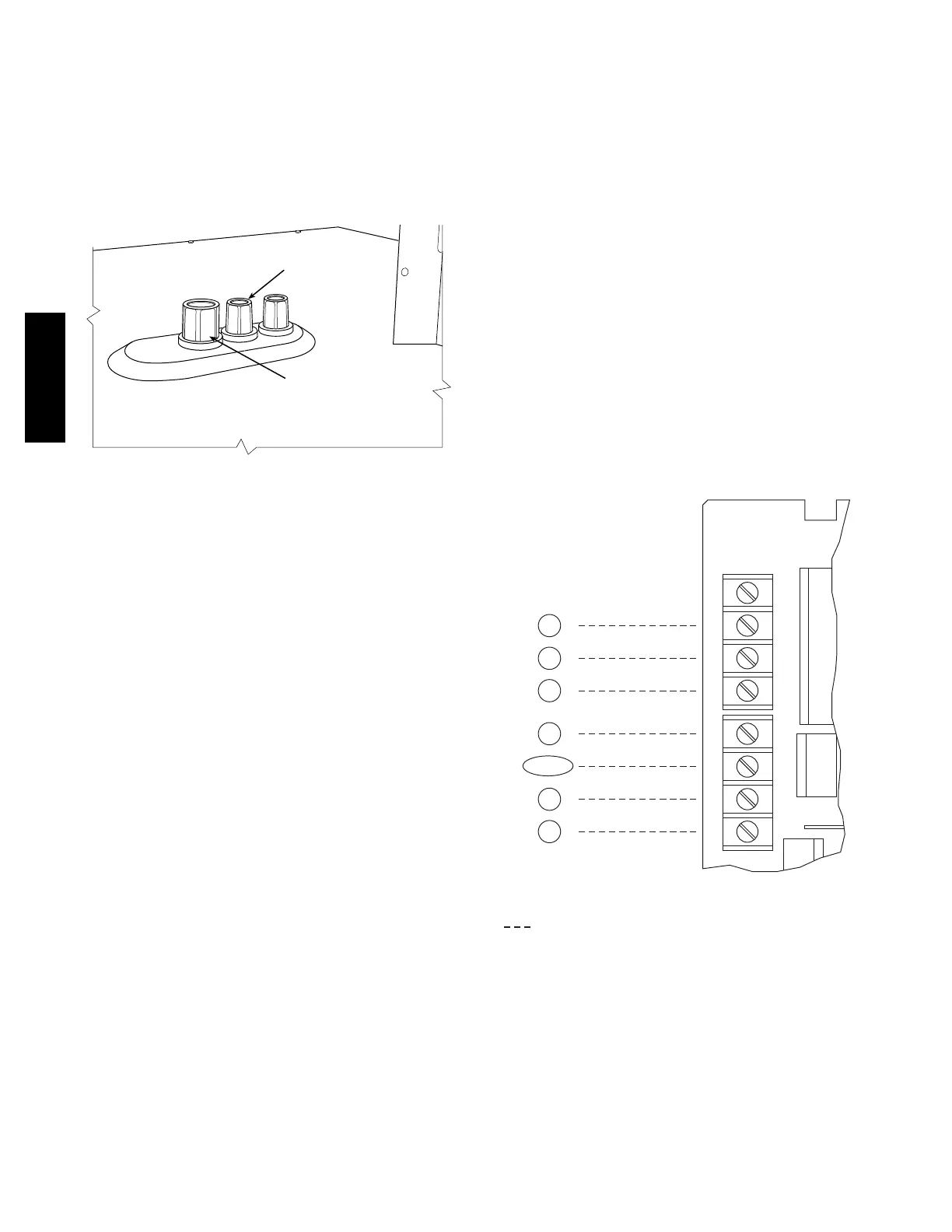
Factory--Option Thru--Base Connections —
This service connection kit consists of a
1
/
2
--in electrical
bulkhea d connector and a 1
1
/
4
--in electrical bulkhead
connec tor, all factory--installed in the embossed (raised)
section of the unit basepan in the condenser sect ion. The
1
/
2
--in bulkhead connector e nables the l ow--voltage control
wires to pass through the basepan. The 1
1
/
4
--in electrical
bulkhea d connector allows the high --voltage power wires
to pass through the basepan. See Fig. 24.
LOW VOLTAGE
CONDUIT
CONNECTOR
HIGH VOLTAGE
CONDUIT
CONNECTOR
C13412
Fig. 24 -- Thru--Base Connection Fittings
Check tightness of connector lock nuts before connecting
electrical conduits.
Field--supplied and field--installed liquidtight conduit
connec tors and conduit may be attached to the connectors
on the basepan. Pull correctly rated high voltage and low
voltage through appropria te conduits. Connect the power
conduit to the internal disconnect (if unit i s so equipped)
or to the external disconnect (through unit side panel). A
hole must be field cut in the main control box bottom on
the left side so the 24--v control connections can be made.
Connect the control power conduit to the unit control box
at this hole.
Units without Thru--Base Connections —
1. Install power wiring conduit through side panel open-
ings. Install conduit between disconne ct and control
box.
2. Install power lines to terminal connections as shown
in Fig. 19.
Field Control Wiring —
The 50TC unit requires an external temperature control
device. This device can be a thermostat (field--supplied) or a
Premier Lin kt contr oller (av ailable as factory--installed
option or as field--installed accessor y, fo r use on a Carrier
Comfort Network or as a stand alone control) or the RTU
Open Contr oller for Bu ildin g Man ag ement Systems using
non--CCN protocols. The RTU Open controller is available
as a factory--installed option only.
Thermostat —
Ins tall a Carrier--approv ed access or y thermos tat accordin g to
installatio n instructio ns included with the access or y. F or
complete economizer fu n ction , select a two--stage cooling
thermostat. Locate the thermos tat access or y on a solid wall
in the conditioned space to sense average temperature in
accordan ce with the thermos tat installation instru ction s .
If the thermostat c ontains a logic circuit requiring 24--v
power, use a thermostat cable or equivalent single leads of
different colors with minimum of seven leads. If the
thermostat does not require a 24--v source (no “C”
connec tion required), use a thermostat cabl e or equivalent
with minimum of six leads. Check the thermostat
installation instruc tions for additional features which
might require addi tional conductors in the cable.
For wire runs up to 50 ft. (15 m), use no. 18 AWG
(American Wire Gage) insulated wire [35_C(95_F)
minimum]. For 50 to 75 ft. (15 to 23 m), use no. 16 AWG
insulated wire [35_C(95_F) minimum]. For over 75 ft.
(23 m), use no. 14 AWG insulated wire [35_C(95_F)
minimum]. All wire siz es larger than no. 18 AWG cannot
be directly connected to the thermostat and will require a
junction box and splice at the thermostat.
Typical
Thermostat
Connections
Central
Terminal
Board
W1
Y2
Y1
R
W2
G
C
X
W1
Y2
Y1
R
W2
G
C
X
T–STAT
C
W2
G
W1
O/B/Y2
R
Y1
(Note 1)
Note 1: Typical multi-function marking. Follow manufacturer’s configuration
instructions to select Y2.
Note 2: W2 connection not required on units with single-stage heating.
Field Wiring
(Note 2)
C09351
Fig. 25 -- Typical Low--Voltage Control Connections
Unit without Thru --Base Connection Kit —
Pass the thermostat control wires through the hole provided
in the end panel (see item “D” in the view labeled “LEFT”
in Fig. 2 and 3); then feed the wires through the raceway
built into the corner post to the control box. Pull the wires
over to the terminal strip on the upper--left corner of the
Centr al Terminal Board. (CTB) See Fig . 26.
50TC

 Loading...


