56
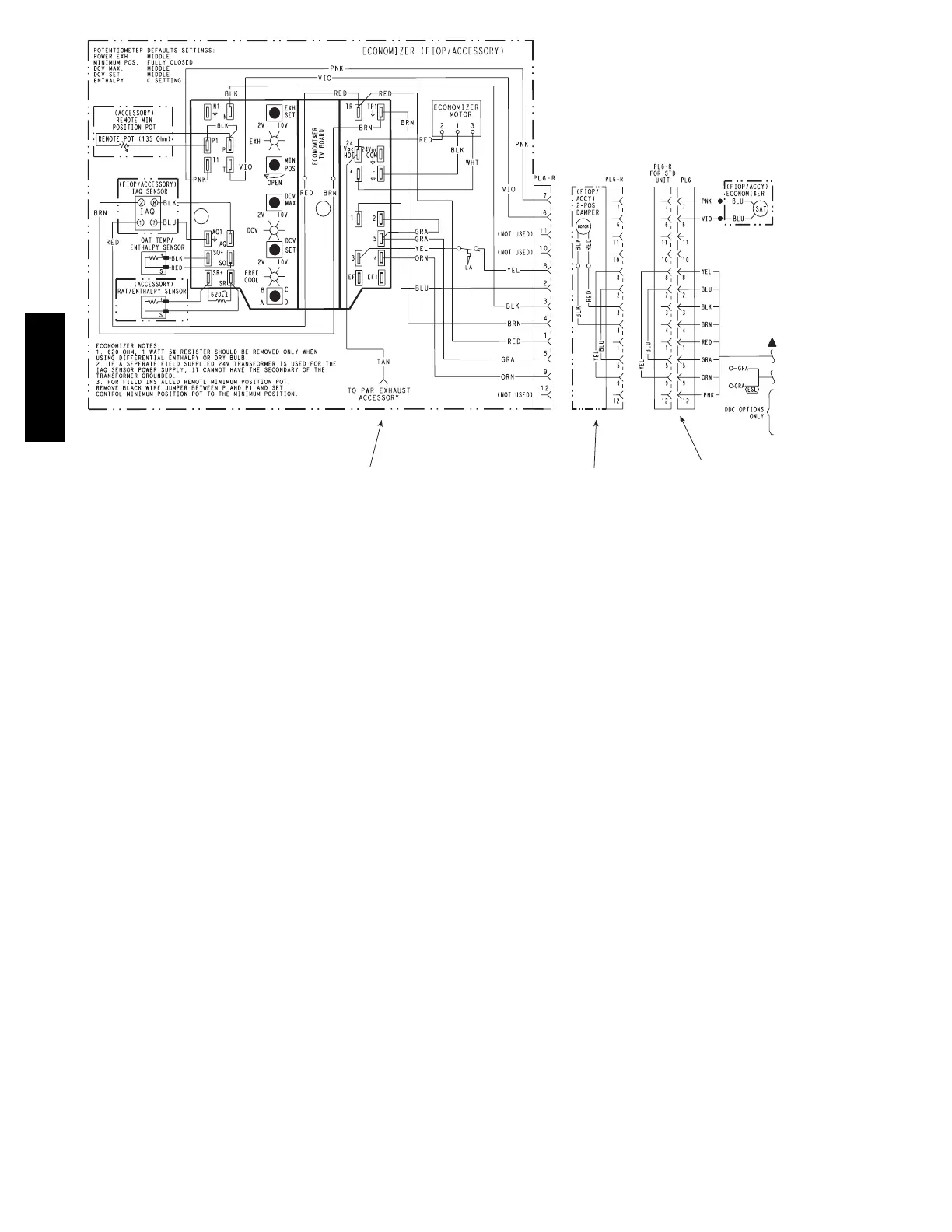
Economizer 2 Position Damper
Unit Without Economizer or
2 Position Damper
C08631
Fig. 76 -- EconoMi$er
R
IV Wiring
Step 11 — Adjust Factory--Installed Options
Smoke Detectors —
Smoke detector(s) will be connected at the Central
Terminal Board (CTB), at terminals marked “Smoke
Shutdown”. Remove jumper JMP 3 when ready to
energize unit.
EconoMi$er IV Occupancy Switch —
Refer to Fig. 76 for general EconoMi$er IV wiring.
External occupa ncy control is managed through a
connection on the Central Terminal Board.
If external occupancy control is desired, connect a time
clock or remotely controlled switch (closed for Occupied,
open for Unoccupi ed sequence) at terminals marked
OCCUPANCY on CTB. Remove or cut jumper JMP 2 to
complete the installation.
Step 12 — Install Accessories
Available accessories include:
Roof Curb
Thru--base connection kit (must be installed bef ore unit
is set on curb)
Manual outside a ir dam per
Two--Position motorized outside air damper
EconoMi$er IV (with control and integrated barome tric
relief)
EconoMi$e r2 (without control/for external signal and
integrated barometric relief)
Power Exhaust
Differential dry--bulb sensor (EconoMi$er IV)
Outdoor enthalpy sensor
Differential enthalpy sensor
Electric Heaters
Single Point kit s
Low Ambient Controls
Thermostat / Sensors
CO
2
sensor
DDC interface (PremierLinkt c ontroller)
Louvere d hail guard
Phase monitor control
Winter Start kit
Refer to separate installation instructions for information
on installing these accessories.
50TC

 Loading...


