65
Appendix A: Technical Reference
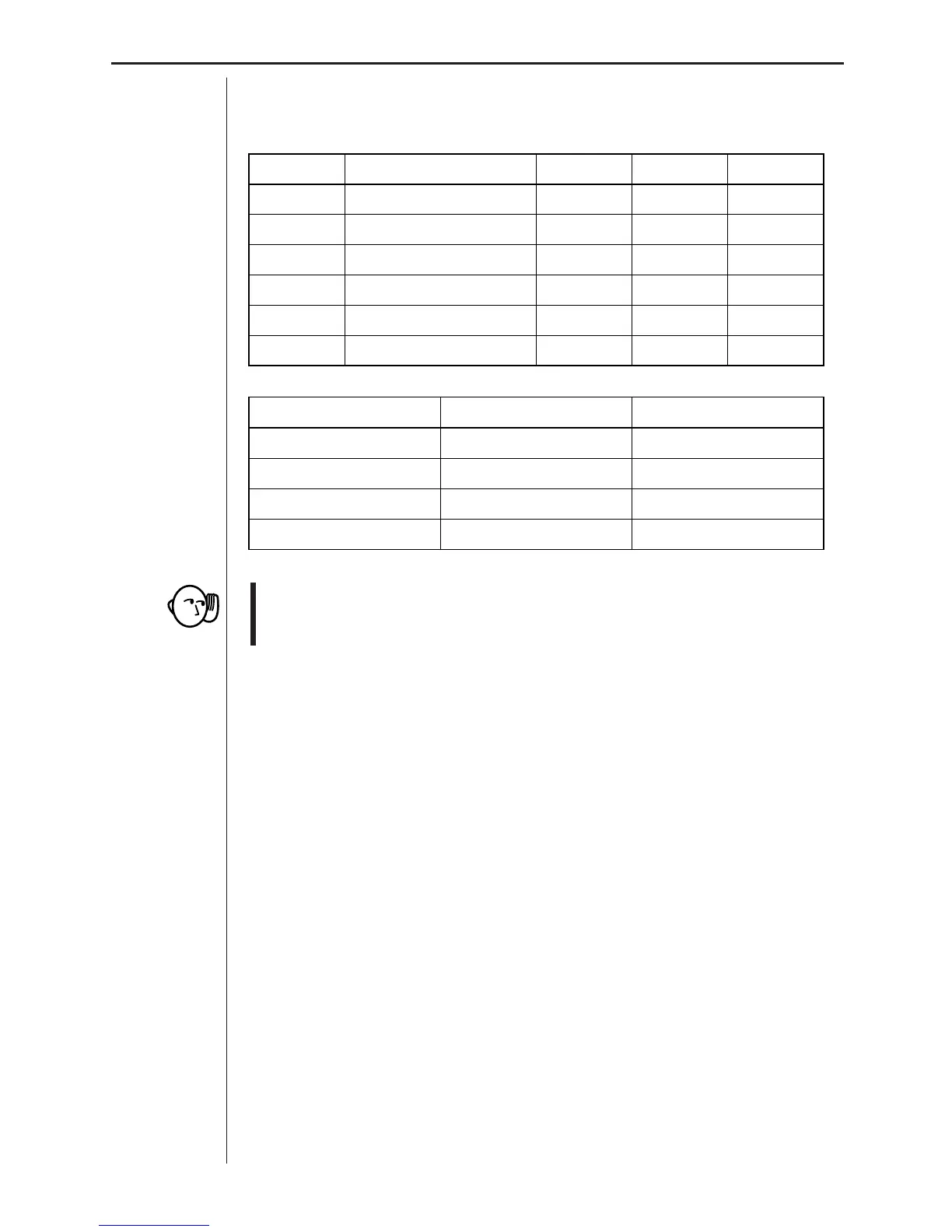
Connector Pinouts
The data analyzer uses British Telecom-type 6-pin probe connectors.
DIG OUTPin CH1, CH2, CH3 SONIC DIG IN
Clock-Out1 Vin Echo Clock-In
Gnd2 Gnd Init Gnd
D0 Out3 Vres Auto-ID D0 In
D1 Out4 Auto-ID +5 Volt DC D1 In
D2 Out5 +5 Volts DC Gnd D2 In
D3 Out6 Vin-low n/a D3 In
Vin Vin-low
Channel CH1, CH2, CH3 CH1, CH2, CH3
Input Signal Analog Data Analog Data
Input Range ±10V 0-5V
Input Impedance 740k! (at 2.0V) 748k! (at 0.03V)
• The data analyzer displays values of 30mV (Vin-low) and 2.0V (Vin) while
there is no probe input. This is a normal operation to indicate internal
system voltage.
Vres: ..................... Output reference voltage from the data analyzer
through a 15k! resistor. When using this function,
Vres should be connected to Vin-low and measure-
ment should be between Vin-low and Gnd.
Gnd: ..................... Ground (common for all channels)
Auto-ID: ................ Auto-ID probe detection data input (Auto-ID resistor
connected from pin 4 to ground)
Echo: .................... Distance sensor input
Init: ....................... Distance initialization signal
Clock-In: ............... External clock signal input (digital)
D0 In to D3 In: ...... Input pins for digital input signals
Clock-Out: ............ Clock output (digital)
D0
Out to D3 Out: . Output pins for digital output signals
 Loading...