EasyManua.ls Logo

Casio PX-110 User Manual

Casio PX-110
65 pages
To Next Page IconTo Next Page
To Previous Page IconTo Previous Page
Page #31 background imageLoading...
Page #31 background image
31
iiB (Binary) = index length
"index length (iiB)" indicates the index field length, which is always the following, regardless of the "act" (Action)
value.
iiB......index byte size - 1
dddddB (Binary) = data length
"data length (dddddB)" indicates the size of each data unit (parameter) in the "data" field.
The data length differs according to Message Type, as shown below.
15.2.9 9....ps : Parameter Set Number
This field is a 2-byte (LSB, MSB) value indicating the number of the parameter set (00mmmmmmmnnnnnnnB,
binary) being transferred.
15.2.10 10...index Parameter Index Number
This field contains a supplementary number that points to data when parameters are arrayed. The meaning is
different for each parameter, and the length can be anywhere from one to four bytes.
Even when parameters have the same IDs, for example, as when the parameters also have preset numbers, part
numbers, and key numbers, parameters can be distinguished by specifying these values with an "index".
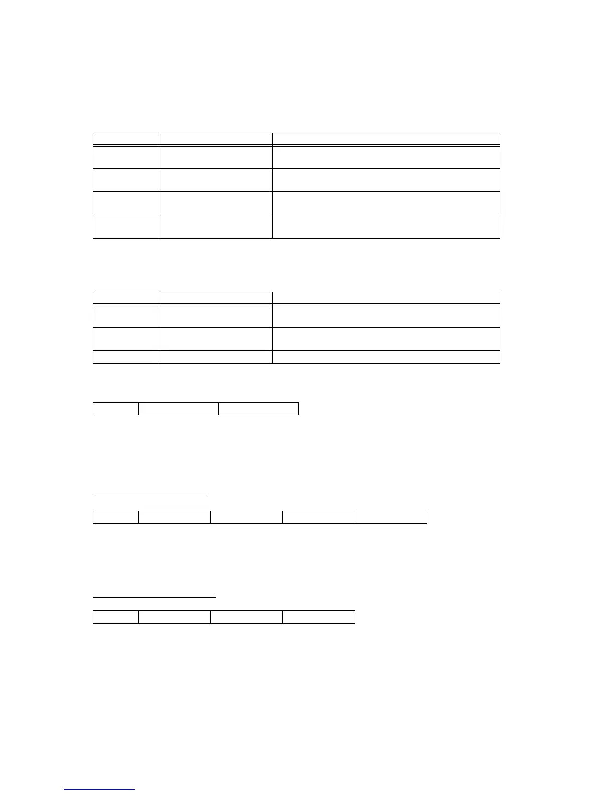
"act" Value Message Type iiB
00, 01 IPC, IPR index byte size - 1
(Example: When 4 bytes = 3)
02, 04 BDS, HDS 2 = 10B
(Packet Number = 3 bytes)
03, 05 BDR, HDR 0 = 00B
(This field is empty, but its length is indicated as 0.)
07 Control 0 = 00B
(The length of this filed is 1 byte.)
"act" Value Message Type dddddB
00 IPC data bit size - 1
(If 1 bit = 00000B; if 32 bits = 11111B)
02, 04 BDS, HDS data bit size - 1 = 01111B
(Transfer is in 16-bit units, so)
01, 03, 05, 07 IPR, BDR, HDR or Control 0
Format: 0nnnnnnnB (LSB) 0mmmmmmmB (MSB)
When act = 00(IPC) or 01(IPR)
Format: 0iiiiiiiB (0jjjjjjjB) (0kkkkkkkB) (0lllllllB)
When act = 02(BDS) or 04(HDS)
Format: 0nnnnnnnB 0NNNNNNNB 0LLLLLLLB

Table of Contents

Other manuals for Casio PX-110

Question and Answer IconNeed help?

Do you have a question about the Casio PX-110 and is the answer not in the manual?

Casio PX-110 Specifications

General IconGeneral
Polyphony32 notes
Speakers2 x 12cm
Amplifier Output8W + 8W
Digital EffectsReverb, Chorus
Touch Sensitivity3 levels, Off
MetronomeYes
TransposeYes
TuningYes
Pedals1 (Sustain)
ConnectorsHeadphone, Pedal
Power SupplyAC adapter (AD-12)
Included AccessoriesAC adapter
Keyboard Type88-key weighted hammer action

Summary

Part I MIDI Message Overview

1 Product Configuration as a MIDI Device

Describes the instrument's configuration as a MIDI device, including controller and sound source blocks.

2 Different Operations Depending on Part Mode

Explains how operations differ based on the selected Part Mode for sound source operations.

Part II Channel Message

3 Receive Channel

Details how the instrument receives channel messages and the channel numbers used by each part.

5 Note Off

Explains the MIDI Note Off message format, send, and receive operations.

8 Control Change

Covers the Control Change message format and its various controller numbers for parameter manipulation.

10 Program Change

Details the Program Change message for selecting tones and its relation to Bank Select.

Part III System Message

13 Active Sensing

Describes the Active Sensing system message, its function, and mode entry.

14 System Exclusive Message

Introduces System Exclusive messages, including Universal and instrument-specific formats.

Part IV PX-110/PX-310/PX-700 System Exclusive Message

15 Format

Details the structure and classification of PX-110/PX-310/PX-700 System Exclusive messages.

17 Parameter Set Transfer Modes (PX-310)

17.1 Communication Modes

Explains communication modes like One-way and Handshake for parameter set transfer.

17.3 Handshake Mode Communication Flow

Details the communication flow for Handshake mode parameter set transfer, including error handling.

Part V Parameter List

18 Command Parameter

Lists parameters that execute commands and indicate statuses, including system and data management parameters.

19 Patch Parameter

Describes patch parameters for controlling sound source operation mode and common settings.

Part VI Parameter Set List

21 SMF Parameter Set (PX-310)

Details SMF parameter sets that can be transferred via System Exclusive Bulk Dump.

22 About Parameter Set (PS) numbers

Explains how user Parameter Set numbers are categorized and located.

Part VII DSP Parameter List

23 DSP Algorithm List (Single Effect)

Lists parameters for individual DSP algorithms, detailing settings for effects like Auto Pan, Tremolo, and EQ.

24 DSP Algorithm List (Multi Effect)

Lists multi-effect DSP algorithms as combinations of single effects, detailing their parameters.

Part VIII Setting Values and Send/Receive Values

25 Setting Value Table

Provides tables for various setting value ranges, crucial for understanding parameter mapping.

Part IX MIDI Implementation Notation

25.19 Hexadecimal Notation

Explains the use of hexadecimal notation in MIDI implementation data.

25.20 Binary Notation

Explains the use of binary notation in MIDI implementation data.

Related product manuals