14
Εγκατάσταση Installation
PIGMA/PIGMA SYSTEM
Ηλεκτρικέ συνδέσει
Τροφοδοσία 230 V + σύνδεση γείωση
Η σύνδεση διενεργείται ε ένα καλώδιο 2 P + T παρεχόενο ε το
λέβητα, συνδεδεένο στην κύρια κάρτα στο εσωτερικό του πίνακα
χειριστηρίων.
Electrical connections
230 V power supply + earth connection
The connection must be carried out using the 2P + E cable supplied
with the boiler and connected to the main PCB.
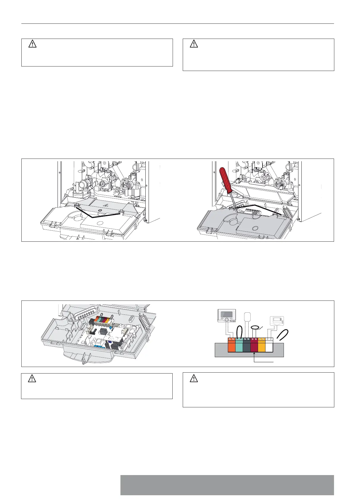
Σύνδεση περιφερειακών
Για την πρόσβαση στι συνδέσει των περιφερειακών:
- αποσυνδέστε ηλεκτρικά το λέβητα
- αφαιρέστε το κάλυα ξεκουπώνοντα το από τον πίνακα οργάνων
- Περιστρέψτε τον πίνακα ελέγχου ενώ τον τραβάτε προ τα προ
- Ξεκλειδώστε τα 2 κλιπ “a”, περιστρέψτε το κάλυα “b” για να έχετε
πρόσβαση στι συνδέσει των περιφερειακών.
- Ξεβιδώστε τι δύο βίδε “c” και αφαιρέστε το κάλυα “d” του πίνακα
οργάνων για φτάσετε στην πλακέτα.
Peripheral unit connection
To access peripheral unit connections carry out the following steps:
- Disconnect the boiler from the power supply
- Remove the casing by unhooking it from the instrument panel
- Rotate the control panel while pulling it forwards
- Unhook the two clips “a”, rotate the cover “b” to have access to the
peripherical connections
- Unscrew the two screws “c” and remove the cover “d” of the
instrument panel to have access to the main P.C.B.
a
b
c
d
Σύνδεση περιφερειακών
Σύνδεση περιφερειακών
BUS = Σύνδεση χειριστηρίου αποστάσεω ( αναλογική συσκευή)
TA2 = θεροστάτη περιβάλλοντο 2
SE = Εξωτερικού αισθητήρα
TNK = Αισθητήρα θεροσίφωνα - PIGMA SYSTEM
SOL = Αισθητήρα θεροκρασία ηλιακού
TA1 = θεροστάτη περιβάλλοντο 1
Peripheral connections:
BUS = Remote control connection
TA2 = Room thermostat 2
SE = Outdoor sensor
TNK = TANK temperature probe - PIGMA SYSTEM
SOL = Solar temperature probe
TA1 = Room thermostat 1
Σύνδεση θεροστάτη περιβάλλοντο
- Τοποθετήστε το καλώδιο του θεροστάτη
- Λασκάρετε το σφιγκτήρα καλωδίου ε ένα κατσαβίδι και
τοποθετήστε ένα-ένα τα καλώδια από τον θεροστάτη
περιβάλλοντο
- Βεβαιωθείτε ότι έχουν συνδεθεί σωστά και δεν τεντώνονται
κλείνοντα ή ανοίγοντα τον πίνακα οργάνων
- Κλείστε το καπάκι, κλείστε τον πίνακα οργάνων και το κάλυα
τη πρόσοψη.
Room thermostat connection
- Introduce the thermostat wire
- Loosen the cable clamp using a screwdriver and insert the wires
leading from the room thermostat one at a time.
- Connect the wires to the terminals TA1, removing the jumper
- Make sure that they are well connected and that they are not subject
to traction when the control panel lid is opened or closed
- Close the ap again, then replace the control panel cover and the
front casing.
Πριν από οποιαδήποτε επέβαση στο λέβητα διακόψτε
την ηλεκτρική τροφοδοσία έσω του εξωτερικού διπολικού
διακόπτη.
Προσοχή!
Για τη σύνδεση και την τοποθέτηση των καλωδίων των προαιρετικών
περιφερειακών συβουλευθείτε τι οδηγίε για την εγκατάστασή του.
WARNING
Before performing any work on the boiler, rst disconnect it
from the electrical power supply using the external bipolar
switch.
Caution!
For the connection and positioning of the wires belonging to
optional peripheral units, please refer to the advice relating to
the installation of these units.
BUS
T
B
TA2
SE TNK
SOL
TA1
BUS
TB
TA2
SE TNK SOL TA1
CN1
Τηλεχειριστήριο
Remote Control
PIGMA SYSTEM
Εξωτερικού αισθητήρα
External sensor
θεροστάτη περιβάλλοντο 1
Room thermostat 1
Αισθητήρα
θεροσίφωνα
Tank temp. probe
OK
Sensys
1234567
 Loading...