5-3
Cisco 1900 Series Hardware Installation
OL-19084-01
Chapter 5 Cable Connection Procedures for Cisco 1900 Series Routers
Connecting to a Console Terminal or Modem
Connection Procedures and Precautions
Connect each WAN and LAN cable to the appropriate connector on the chassis or interface card.
• Position the cables carefully, so that they do not put strain on the connectors.
• Organize the cables in bundles so that cables do not intertwine.
• Inspect the cables to make sure that the routing and bend radiuses are satisfactory. Reposition the
cables, if necessary.
• Install cable ties in accordance with your site requirements.
For cable pinouts, refer to the online document Cisco Modular Access Router Cable Specifications.
Connecting to a Console Terminal or Modem
Your router has asynchronous serial, USB, console and auxiliary ports. These ports provide
administrative access to your router either locally (with a console terminal or PC) or remotely (with a
modem).
The following cables and adapters may be used for connecting your router to a console terminal, PC, or
modem:
• USB Console cable—USB 5-pin mini Type-B to USB Type-A. See “USB Serial Console” section
on page 3-2 for port details and “Specifications” section on page 1-14.
• Console cable— EIA RJ-45 to DB-9
• Modem adapter—DB-9 to DB-25
Note The first time a Windows based PC is connected to the router, a USB device driver must be installed.
See Installing the Cisco Microsoft Windows USB Device Driver, page 5-6.
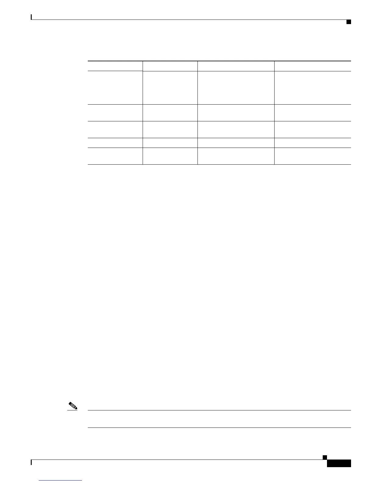
DSL RJ-11C/RJ-14C Network demarcation
device for service provider’s
DSL interface.
RJ-11 straight-through for
2-wire
RJ-14 straight-through for
4-wire
BRI S/T WAN
(external NT1
2
)
RJ-45, orange NT1 device or PINX
3
RJ-45 straight-through
BRI U WAN
(built-in NT1)
RJ-49C/CA-A11,
orange
ISDN network RJ-49 straight-through
Analog modem RJ-11 PSTN RJ-11 straight-through
56/64-kbps
CSU/DSU
8-pin modular RJ-48S interface. RJ-48 straight-through.
1. The color codes are specific to cables shipped by Cisco
2. NT1 = Network Termination 1
3. PINX = Private integrated network exchange
Table 5-1 WAN and LAN Connections (continued)
Port or Connection Port Type, Color
1
Connected to: Cable
 Loading...