5-22
Cisco 2900 Series and 3900 Series Hardware Installation Guide
OL-18712-03
Chapter 5 Installing and Upgrading Internal Modules and FRUs
Installing and Removing PVDM3
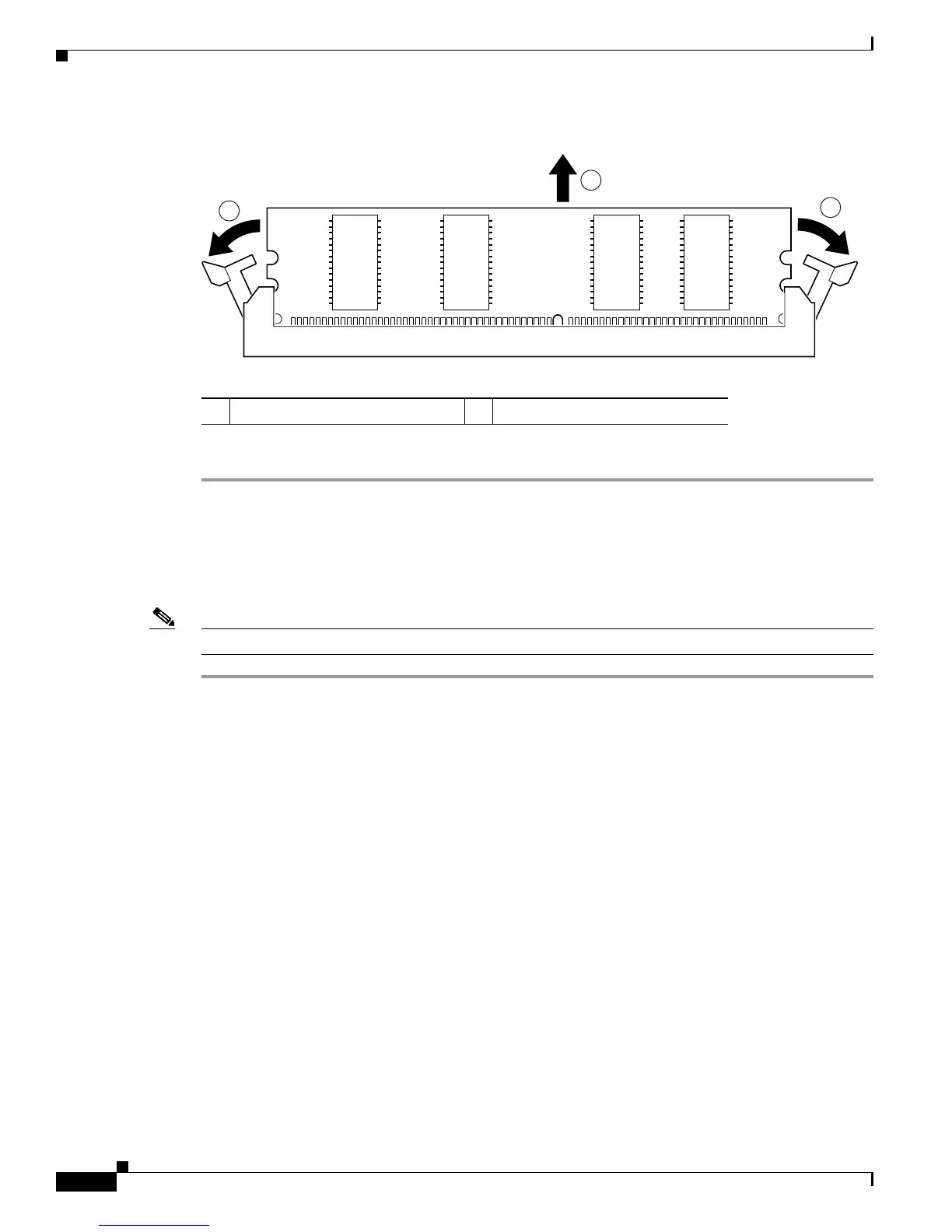
Figure 5-16 Removing a PVDM3
Step 4
Place the PVDM3 in an antistatic bag to protect it from ESD damage.
Installing a PVDM3
To install a PVDM3, follow these steps.
Note Fill PVDM3s slots sequentially, starting with connector 0.
Step 1 Read the “Safety Warnings” section on page 5-2 section and disconnect the power supply before you
perform any module replacement.
Step 2 Locate the PVDM3 connector on the system board. See the “Locating Internal Modules” section on
page 5-7 for the PVDM3 locations.
Step 3 Orient the PVDM3 so that the polarization notch lines up with the polarization key on the connector. See
Figure 5-17.
1 Pull away the retaining clips 2 Pull out the PVDM3
 Loading...