5-49
Cisco 2900 Series and 3900 Series Hardware Installation Guide
OL-18712-03
Chapter 5 Installing and Upgrading Internal Modules and FRUs
Replacing a Fan Tray or Air Filter
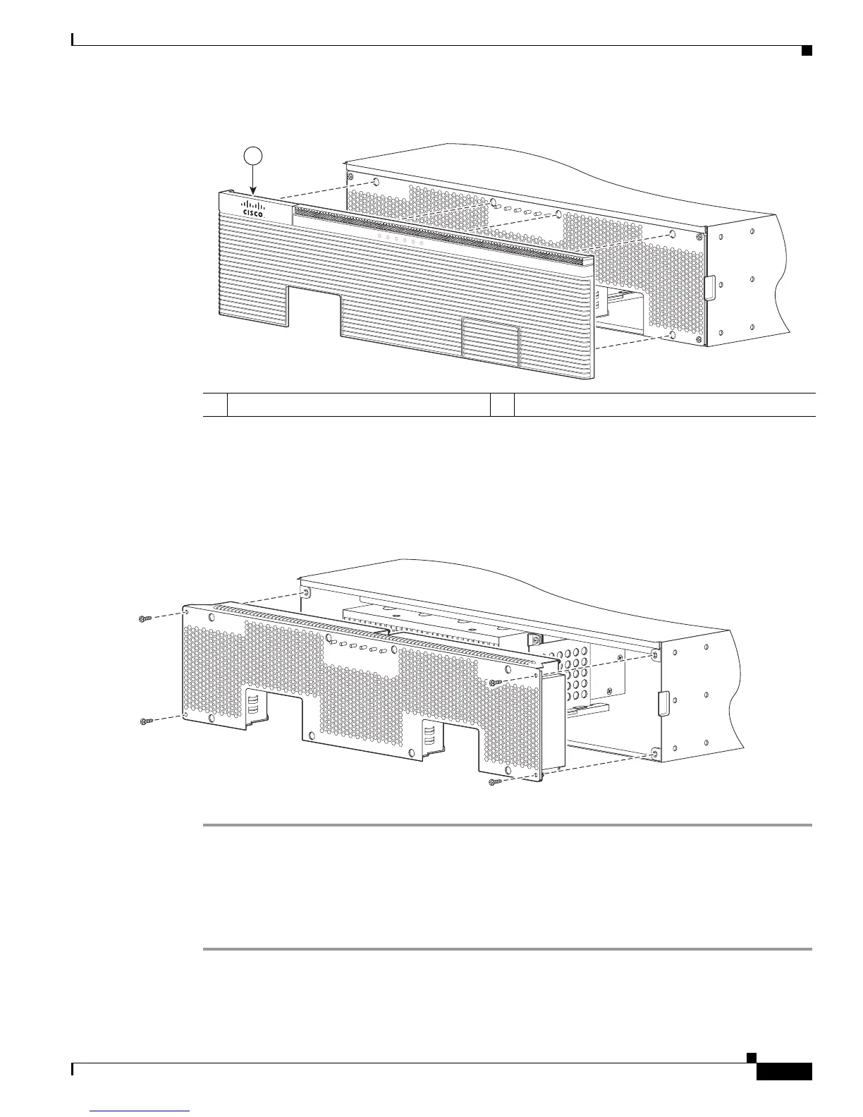
Figure 5-36 Removing the Cisco 3900 Series Router Bezel
Step 3 Loosen the four captive screws on the fan tray.
Step 4 Pull out the fan tray.
Step 5 Insert the replacement fan tray, and tighten the four captive screws as shown in Figure 5-37.
Figure 5-37 Cisco 3900 Series Fan Tray Replacement
Step 6
Snap the bezel in place.
Replacing the Cisco 3900 Series Air Filter
Perform the following steps to replace the air filter:
Step 1 Read the “Safety Warnings” section on page 5-2 section and disconnect the power supply before you
perform any module replacement.
Step 2 Unsnap the bezel by pulling it straight out from the chassis. See Figure 5-38.
1 Bezel
250920
SYS AC T
SYS
PW
R
1
AUX
PWR1
SYS
PW
R
2
AUX
PW
R
2
Cisco 3900 Series
1
 Loading...