5-43
Cisco 2900 Series and 3900 Series Hardware Installation Guide
OL-18712-03
Chapter 5 Installing and Upgrading Internal Modules and FRUs
Replacing Power Supplies and Redundant Power Supplies
Installing an RPS Adapter
To install an RPS adapter, perform the following steps:
Caution The RPS adapter must be in the router chassis before connecting to the RPS.
Step 1 Read the “Safety Warnings” section on page 5-2 section and disconnect the power supply before you
perform any module replacement.
Step 2 Ensure AC or DC power is disconnected from the router power supply.
Step 3 If connected, place the RPS 2300 into standby mode. Consult the Cisco Redundant Power System 2300
Hardware Installation Guide for operating the RPS 2300.
Step 4 If an RPS Adapter had never been installed, a blank panel is in its place. Remove the RPS Adapter blank
panel.
Step 5 Insert the RPS adapter into the router (Figure 5-29 or Figure 5-30) and tighten the screws.
Step 6 Connect the RPS 2300 cable into the RPS adapter connector.
Step 7 Connect the other end of the RPS 2300 cable to the RPS 2300.
Step 8 Power up the router.
Step 9 Place the RPS into Active mode.
Removing an RPS Adapter
To remove an RPS adapter, perform the following steps:
Step 1 Read the Safety Warnings section and disconnect the power supply before you perform any module
replacement.
Step 2 If connected, place the RPS 2300 into standby mode. Consult the Cisco Redundant Power System 2300
Hardware Installation Guide for operating the RPS 2300.
Step 3 Power off and disconnect the AC or DC power from the router power supply.
Step 4 Remove the RPS cable from the RPS 2300.
Step 5 Remove the other end of the RPS 2300 cable from the RPS adapter.
Step 6 Remove the RPS adapter.
2911 in POE
Boost
0112
2921, 2951 in
POE Boost
0101
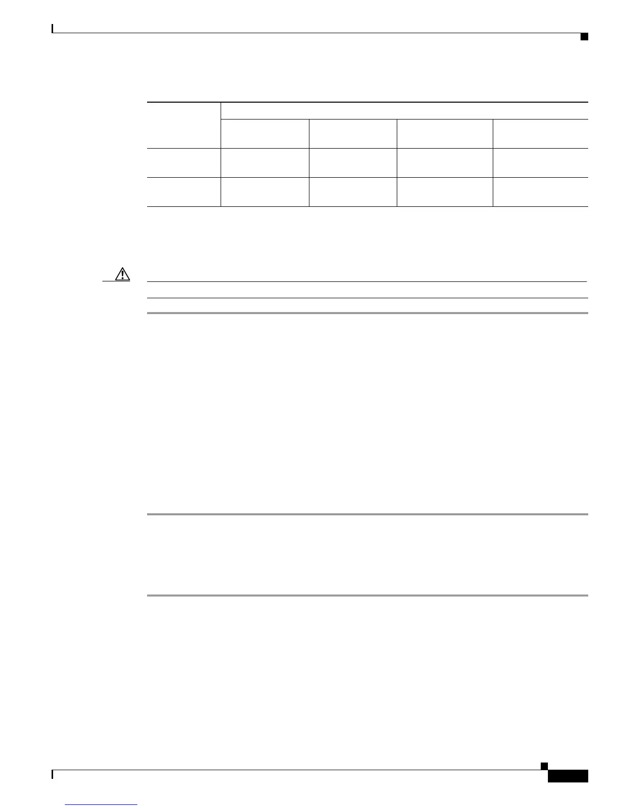
Table 5-3 RPS 2300 Backup Capabilities (continued)
Power Mode
Quantity and Type of RPS 2300 FRU
Quantity 1
C3K-PWR-750WAC
Quantity 2
C3K-PWR-750WAC
Quantity 1
C3K-PWR-1150WAC
Quantity 2
C3K-PWR-1150WAC
 Loading...