5-47
Cisco 2900 Series and 3900 Series Hardware Installation Guide
OL-18712-03
Chapter 5 Installing and Upgrading Internal Modules and FRUs
Replacing a Fan Tray or Air Filter
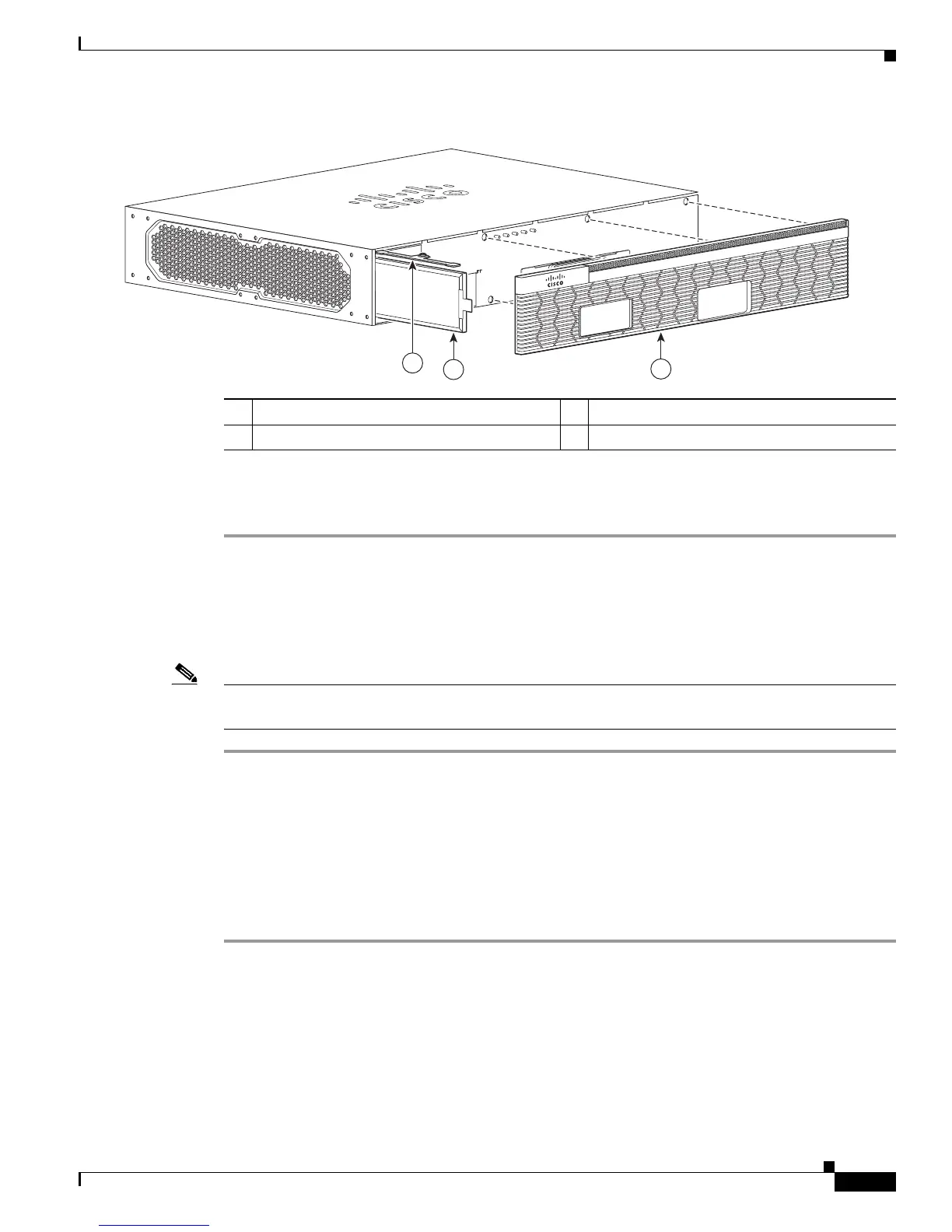
Figure 5-34 Cisco 2911 Filter Replacement
Step 3
Remove the screw from the air filter cover and remove the filter.
Step 4 Install the replacement air filter, the air filter cover, and the bezel
.
Replacing the Cisco 2921 or 2951 Fan Tray
To replace the fan tray, complete the following steps:
Note If hot-swapping the fan tray, it is recommended to complete the operation within two minutes to ensure
the router remains within operating temperature. See Figure 5-35.
Step 1 Read the “Safety Warnings” section on page 5-2 section and disconnect the power supply before you
perform any module replacement.
Step 2 Pry open the fan tray screw covers on the four captive fan tray screws.
Step 3 Completely loosen the four captive fan tray screws.
Step 4 Pull the fan tray out.
Step 5 Insert the replacement fan tray and tighten the four captive screws.
Step 6 Snap the screw covers in place.
1 Filter 2 Filter cover
3 Bezel
 Loading...