5-39
Cisco 2900 Series and 3900 Series Hardware Installation Guide
OL-18712-03
Chapter 5 Installing and Upgrading Internal Modules and FRUs
Replacing Power Supplies and Redundant Power Supplies
Step 2 Remove the bezel.
Step 3 Loosen the four captive screws on each corner of the fan tray and pull out the fan tray. See Figure 5-31.
Step 4 Loosen the two captive screws on the power supply module. See Figure 5-31.
Step 5 Pull on the two captive power supply fastening screws to leverage the power supply from its connector,
and then slide the power supply module out of the chassis.
Step 6 Insert the replacement power supply module, and tighten the captive screws.
Step 7 Reinstall the fan tray and bezel.
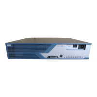
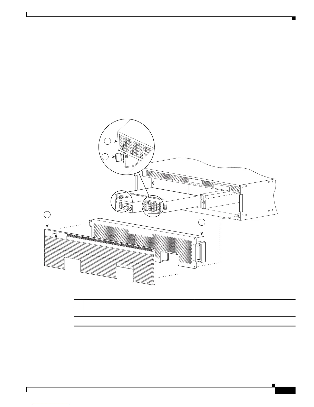
Figure 5-31 Cisco 3900 Series Power Supply Components
Inserting POE supply in an Ethernet Switch Network Module
The POE power supply for Ethernet Switch Network Modules supports online insertion feature. The
POE power supply does not support online removal.
343266
1
4
2
3
SYS
ACT
SYS
PWR1
AUX
PWR1
SYS
PWR2
AUX
PWR2
Cisco
2900 Series
1 Bezel 2 Power supply
3 Power supply fastening screws (2) 4 Fan tray
 Loading...