B-2
Cisco Content Delivery Engine 205/220/250/280/285/420/460/475 Hardware Installation Guide
Appendix B Connector Pin Assignments
Serial Console-Interface Connector Pin Assignments
Serial Port Connector
The CDEs have one standard serial port connector located on the back of the device.
Note The CDE280 Engine uses a KVM console or CIMC virtual console. For more information on
the KVM console, see the “KVM Console” section on page B-3
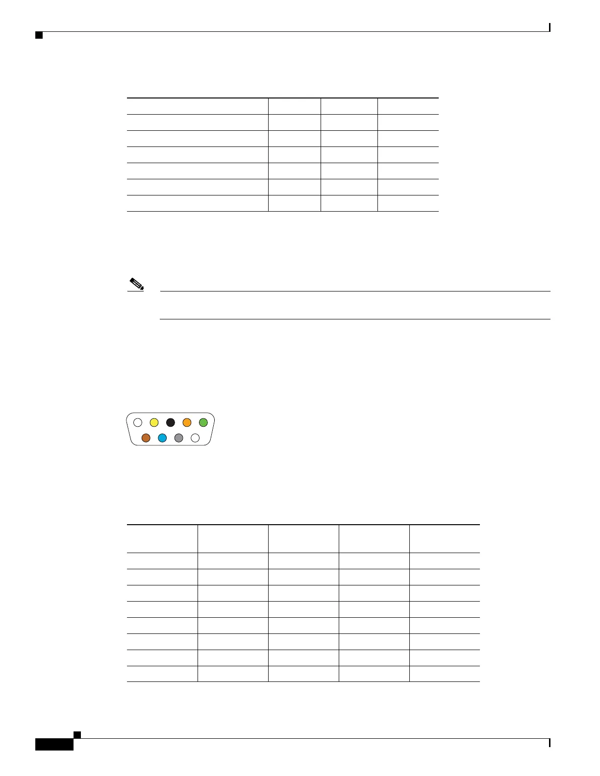
Figure B-1 shows the pin number assignments for the 9-pin, male D-shell serial port connector on the
back of the device. These pin number assignments conform to the industry standard for RS-232
communications.
Figure B-1 Serial Port Connector
Table B-3 provides the RJ-45-to-DB-9 pinout information for the interconnections between the terminal
server and a CDE.
Interface signal ground 4 — GND
Interface signal ground 5 — GND
Receive Data; input 6 In RXD
Ready to send; output 7 Out RTS
Data Set Ready; input 8 In DSR
Clear to Send; input 9 In CTS
Table B-2 RJ-45 Connector Pin Assignments (continued)
Description Pin I/O Signal Name
Table B-3 RJ-45 Connector to DB-9 Pinout
Signal Name/
Function RJ-45 Pin RJ-45 DB-9 Pin
Signal Name/
Function
TXD 6 Yellow 2 RXD
RXD 3 Black 3 TXD
DSR 2 Orange 4 DTR
GND 5 Green 5 GND
DTR 7 Brown 6 DSR
RTS 1 Blue 7 CTS
CTS 8 Slate/Grey 8 RTS
GND 4 Red — GND
 Loading...