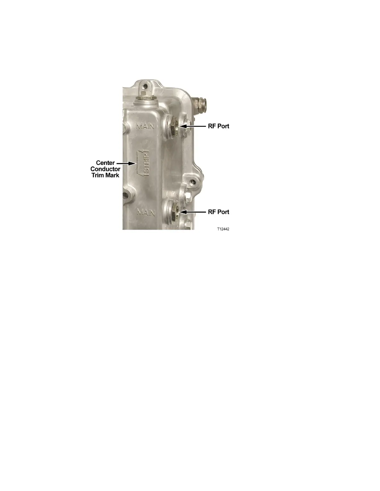
2 If the center conductor extends past the STRIP line on the housing, trim the pin
flush with the STRIP line.
3 Remove any burrs or sharp edges from the trimmed end of the pin.
Connecting the RF Cables to the Node Housing
Follow these steps to connect the RF cables.
1 Determine which ports receive an RF cable for your configuration.
2 The length of the RF connector center pin is critical to proper operation. The pin
length must be 1.6 inches (4.064 cm). Trim pin if necessary before installation. See
Trimming the Center Conductor (on page 82).
Note: Assemble each RF connector to its cable according to manufacturer’s
instructions.
3 Remove the sealing plug of each port to which cables connect. Note that Ports 1,
3, 4, and 6 have the option of a vertical or horizontal connection.
4 Insert the appropriate coaxial connector of each RF cable to the desired housing
port and torque to the manufacturer’s specification. Do not exceed recommended
torque.
5 Repeat steps 2 through 4 for each RF port used.
6 Continue to Applying Power to the Node.
 Loading...


