Chapter 2 Theory of Operation
Reverse Configuration Module
Introduction
The reverse configuration module determines the reverse path topology in the RF
amplifier module and 1.2 GHz GS7000 Node. The input signals from four
independent amplifier module output ports enter the reverse configuration module
where they are combined and/or directed to one to four optical transmitters. The
various types of the reverse configuration module are described below.
4x1 Reverse Configuration Module with Auxiliary Reverse RF Injection
Description
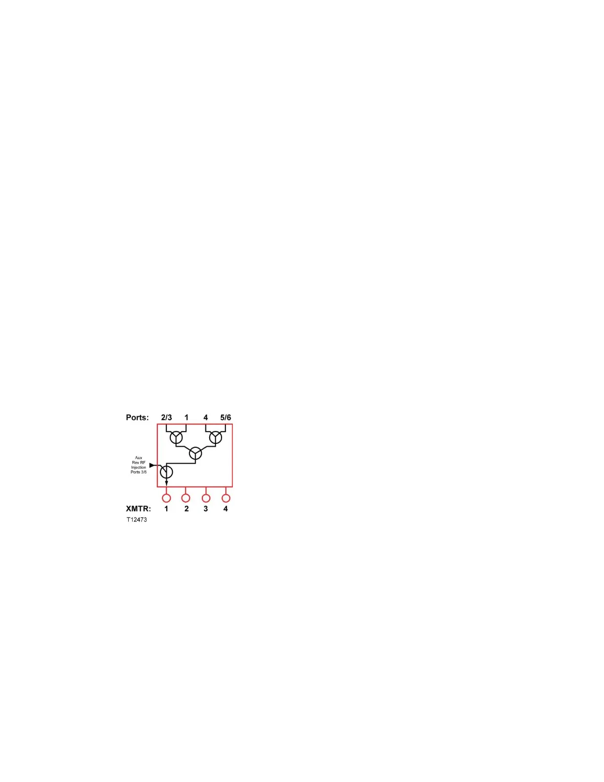
The 4x1 Reverse Configuration Module with auxiliary reverse RF injection combines
all four reverse RF inputs (Ports 1, 2/3, 4, and 5/6) of the node and routes the signal
to Transmitter 1. An RF signal from an external source can optionally be injected and
coupled with the reverse RF inputs on Ports 3/6 and routed to Transmitter 1.
The following diagram shows how this module functions.
4x1 Redundant Reverse Configuration Module Description
The 4x1 Redundant Reverse Configuration Module combines all four reverse RF
signals (Ports 1, 2/3, 4 and 5/6) together, splits this RF signal and routes it to
Transmitters 1 and 2.
The following diagram shows how this module functions.
 Loading...


