4-Way RF Amplifier Module
Note: Shunts are available with both red and black tops. Use red to indicate that
power is applied to that port. Use black to indicate that input power is not
applied.
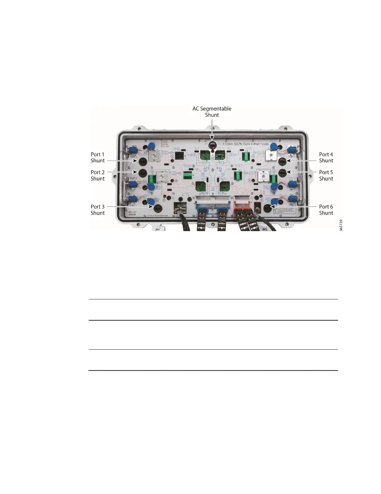
3 If desired, remove shunts to block AC power at the individual ports.
4 The next step depends on the power path, as follows:
power will pass from left side of housing (Ports 1,
2, and 3) to right side of housing (Ports 4, 5, and 6)
ensure that the AC segmentable
shunt is installed.
power is to be blocked between left side of housing
(Ports 1, 2, and 3) and right side of housing (Ports
4, 5 and 6)
ensure that the AC segmentable
shunt is removed.
Ports 1, 2, and 3 are powered from one source and
Ports 4, 5 and 6 are powered from another source
ensure that the AC segmentable
shunt is removed.
5 Continue to Voltage Check Procedure.
Voltage Check Procedure
Always check both AC and DC voltages during initial setup of the 1.2 GHz GS7000
Node.
Follow these steps to check AC and DC voltages.
 Loading...


