Chapter 4 Setup and Operation
4x4 Reverse Configuration Module with Auxiliary Reverse RF Injection
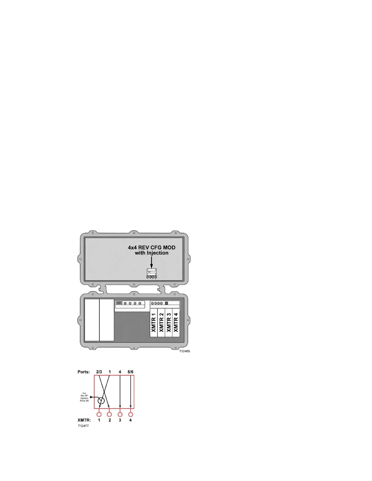
A signal from each port is assigned to a dedicated reverse transmitter. An RF signal
from an external source can optionally be injected and coupled with the reverse RF
inputs from Ports 3/6 and routed to Transmitter 1.
Note: This module is typically used when using multiplexing digital reverse
modules, such as our EDR Digital Reverse Modules. Since the digital reverse module
occupies the physical space that transmitters 3 and 4 used to occupy in the node lid,
only a 6-port optical interface board can be used.
Install modules as follows:
Transmitter dedicated to Port 1 in XMTR 1
Transmitter dedicated to Port 2/3 in XMTR 2
Transmitter dedicated to Port 4 in XMTR 3
Transmitter dedicated to Port 5/6 in XMTR 4
The following diagram illustrates reverse path signal flow in this module.
 Loading...


