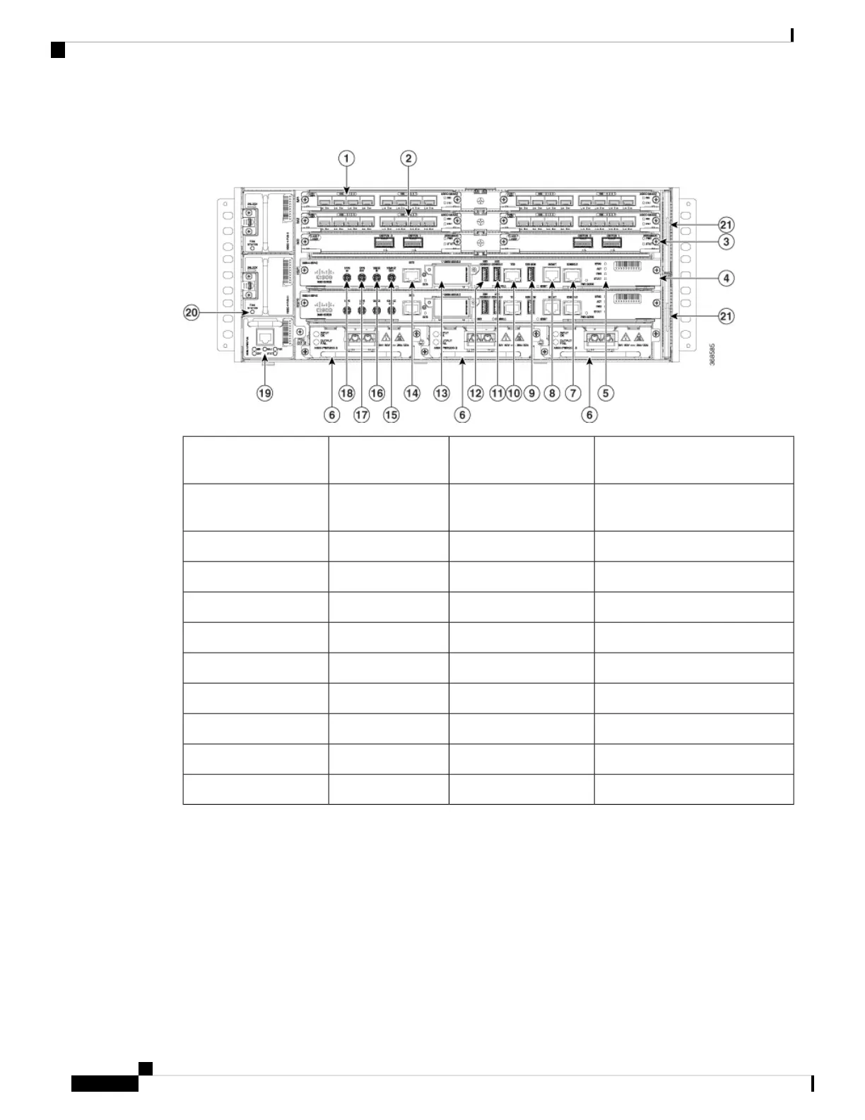
Figure 1: Cisco NCS 560-4 Router Front Panel
Interface module slot2Interface module
slot
1
Route Switch Processor
(N560-4-RSP4E or N560-4-RSP4)
4Interface module
slot
3
Power Supplies (three)6System LEDs5
Management Port8RJ-45 Console7
Time of day timing (ToD) port10USB memory port9
USB console12Auxiliary console11
BITS timing port14GNSS module13
10 MHz In1610 MHz Out15
1PPS In181PPS Out17
Slave fan tray20Master fan tray19
——Fan Filters21
The cabling for all interfaces (power, data and control) are on the front side of the chassis. The chassis grounding
point is located on the rear side of the chassis.
The following image illustrates the slot numbering scheme for the FRUs in Cisco NCS 560-4 router in case
of single width IMs.
Cisco NCS 560-4 Router Hardware Installation Guide
2
Cisco NCS 560-4 Router Overview
Cisco NCS 560-4 Router Features

 Loading...