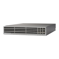
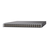
power supply modules on the opposite end of the chassis. Port-side exhaust airflow enters the chassis through
the fan modules and exhausts through the port side of the chassis.
When lifting the chassis, use each of the following guidelines:
•
Disconnect any cables attached to the switch.
•
Ensure that your footing is solid and the weight of the switch is evenly distributed between your feet.
•
Lift the switch slowly, keeping your back straight. Lift with your legs, not with your back. Bend at the
knees, not at the waist.
When installing the switch, follow these guidelines:
•
Record switch and installation information in Site Preparation and Maintenance Records, on page 57
as you install and configure the switch.
•
Ensure that there is adequate space around the switch to allow for servicing the switch and for adequate
airflow (see Clearance Requirements, on page 10 for the switch specifications).
•
Ensure that the switch is going to be positioned with its air intake side positioned in the cold aisle and
its air exhaust positioned in the hot aisle. This enables the switch to be cooled properly. If the air intake
is positioned in a hot aisle, the switch can overheat and shutdown.
•
Ensure that the rack or cabinet meets the requirements listed in Rack Specifications, on page 43.
Jumper power cords are available for use in a cabinet.Note
•
Ensure that the chassis can be adequately grounded. If the switch is not mounted in a grounded rack,
we recommend connecting both the system ground on the chassis and the power supply ground directly
to an earth ground.
•
Ensure that the site power meets the power requirements listed in System Specifications. If available,
you can use an uninterruptible power supply (UPS) to protect against power failures.
Avoid UPS types that use ferroresonant technology. These UPS types can become
unstable with switches that have substantial current draw fluctuations because of
fluctuating data traffid patterns.
Caution
•
Ensure that circuits are sized according to local and national codes and meet the requirements of the
switch (see Planning for Power Requirements, on page 7 for the switch requirements).
To prevent loss of input power, ensure that the total maximum loads on the circuits
supplying power to the switch are within the current ratings for wiring and breakers.
Caution
•
Depending on your power redundancy needs, have outlets or terminals for one or two power sources
close to the rack as follows:
◦
For no power redundancy, have one power source.
◦
For n+1 redundancy, have one or two power sources.
Cisco Nexus 9336PQ ACI-Mode Switch Hardware Installation Guide
12
Installing the Chassis
Preparing to Install the Switch

 Loading...

