6-16
Cisco PIX Security Appliance Hardware Installation Guide
78-15170-03
Chapter 6 PIX 525
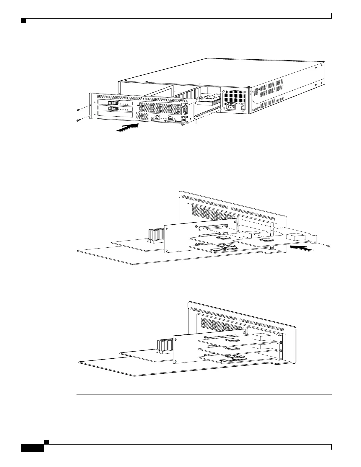
Installing a Circuit Board in the PIX 525
Figure 6-14 The Component Tray at the Back of the PIX 525
Step 3 Remove the screw and cover plate from the circuit board slot.
Step 4 Use Figure 6-15 as a guide to install a circuit board into a PCI slot on the component tray.
Step 5 Attach the screw to hold the circuit board connecting flange to the rear cover plate on the component tray.
Figure 6-15 Inserting an Expansion Board into a PCI Slot on the PIX 525 Component Tray
Step 6 Figure 6-16 shows circuit boards in PCI slots on the component tray.
Figure 6-16 Expansion Boards in PCI Slots on the PIX 525 Component Tray
Step 7
Reinstall the component tray into the PIX 525 chassis.
61908
F
A
I
L
O
V
E
R
100Mbps A
CT
100Mbps ACT
LINK
LINK
10/100 ETHERNET 1
10/100 ETHERNET 0
USB
CONSOLE
P
IX-525
61911
61909

 Loading...


