4-7
Cisco PIX Security Appliance Hardware Installation Guide
78-15170-03
Chapter 4 PIX 515/515E
Installing the PIX 515/515E
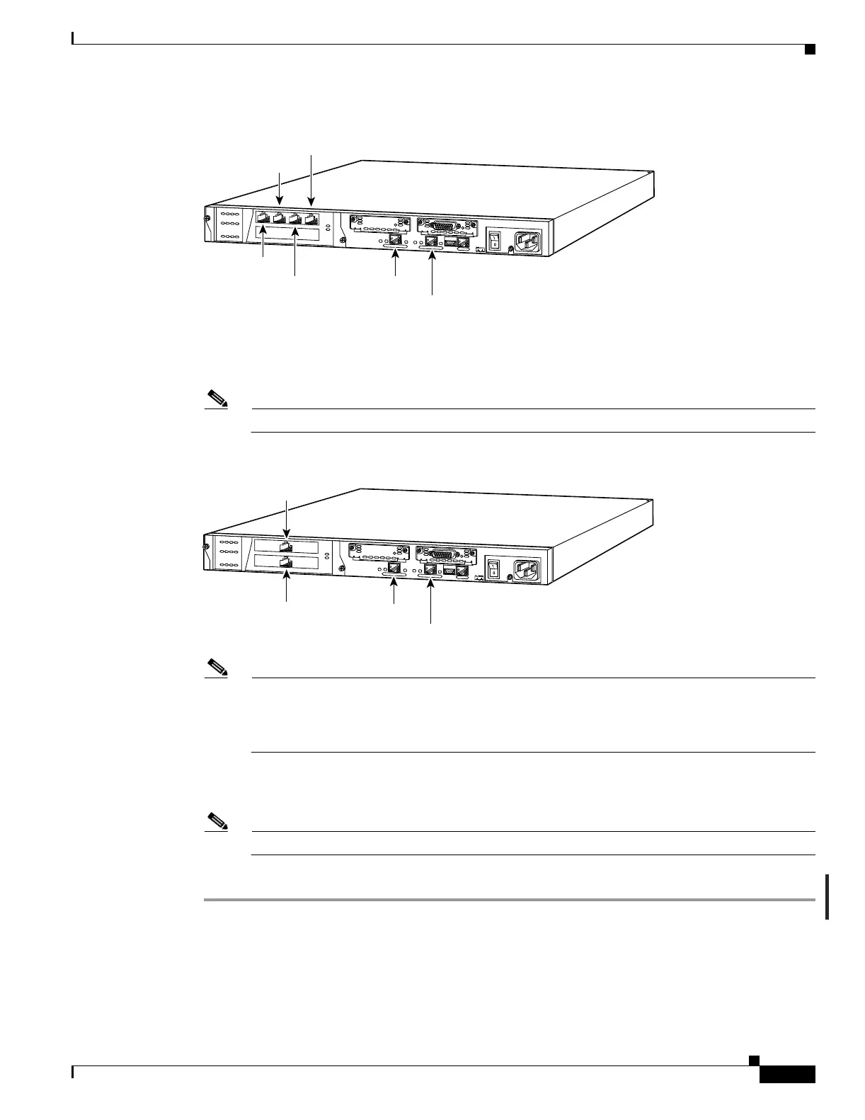
Figure 4-8 Four-Port Ethernet Connectors in the PIX 515/515E
Step 3
Connect the inside, outside, or perimeter network cables to the interface ports. Starting from the top left
the connectors are Ethernet 2, Ethernet 3, Ethernet 4, and Ethernet 5. The maximum number of allowed
interfaces is 6.
Note Do not add a single-port circuit board in the extra slot below the four-port circuit board.
Figure 4-9 Two Single-Port Ethernet Connectors in the PIX 515/515E
Note As shown in Figure 4-9, if your unit has one or two single-port Ethernet circuit boards installed
in the auxiliary assembly on the left of the unit at the rear, the circuit boards are numbered top
to bottom so that the top circuit board is Ethernet 2 and the bottom circuit board is Ethernet 3.
(Additional Ethernet circuit boards require the PIX-515/PIX 515E-UR license to be accessed.)
If you have a second PIX security appliance to use as a failover unit, install the failover feature and cable
as described in the “Installing Failover” section on page 4-9.
Note Do not power on the failover units until the active unit has been configured.
Step 4 Power on the unit from the switch at the rear to start the PIX 515/515E.
D
O
N
O
T
I
N
S
T
A
L
L
I
N
T
E
R
F
A
C
E
C
A
R
D
S
W
I
T
H
P
O
W
E
R
A
P
P
L
I
E
D
C
O
N
S
O
L
E
1
0
/1
0
0
E
T
H
E
R
N
E
T
0
L
in
k
F
D
X
F
D
X
1
0
0
M
b
p
s
L
in
k
1
0
0
M
b
p
s
F
A
IL
O
V
E
R
1
0
/
1
0
0
E
T
H
E
R
N
E
T
1
PIX-515
25733
Ethernet 2
Ethernet 4
Ethernet 1
Ethernet 0
Ethernet 3
Ethernet 5
D
O
N
O
T
I
N
S
T
A
L
L
I
N
T
E
R
F
A
C
E
C
A
R
D
S
W
I
T
H
P
O
W
E
R
A
P
P
L
I
E
D
C
O
N
S
O
L
E
1
0
/
1
0
0
E
T
H
E
R
N
E
T
0
L
in
k
F
D
X
F
D
X
1
0
0
M
b
p
s
L
in
k
1
0
0
M
b
p
s
F
A
IL
O
V
E
R
1
0
/
1
0
0
E
T
H
E
R
N
E
T
1
PIX-515
25734
Ethernet 3
Ethernet 2
Ethernet 1
Ethernet 0

 Loading...


