4-21
Cisco PIX Security Appliance Hardware Installation Guide
78-15170-03
Chapter 4 PIX 515/515E
Installing a Circuit Board in the PIX 515/515E
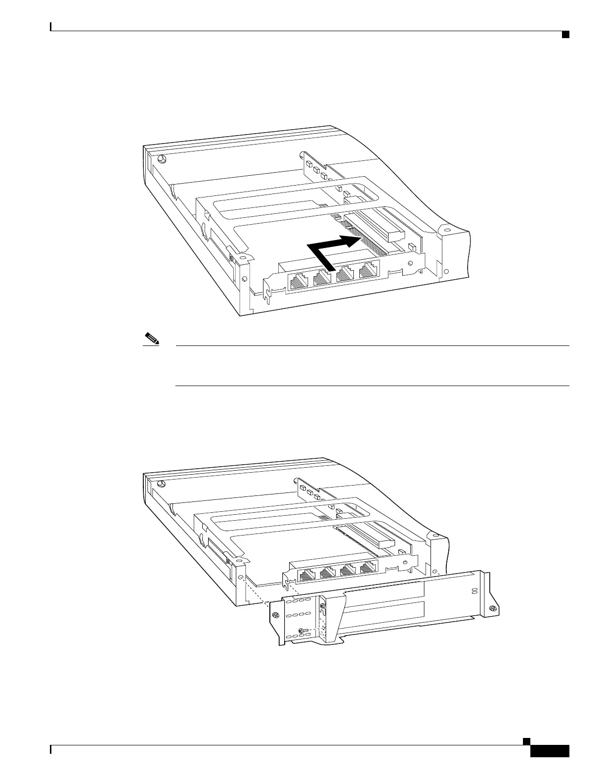
Step 3 Insert a circuit board through the cage opening and into the slot as shown in Figure 4-21.
Figure 4-21 Inserting a Circuit Board into the PIX 515/515E
Note When you insert a four-port Ethernet circuit board in the slot, the end of the circuit board
connector extends past the end of the slot. This does not affect the use or operation of the circuit
board.
Step 4 Attach the back cover plate making sure that the connecting flange on the circuit board goes through the
slot on the back cover plate as shown in Figure 4-22.
Figure 4-22 Attaching PIX 515/515E Back Cover Plate
Step 5
Attach the screw to hold the circuit board connecting flange to the cover plate, and install the screws to
attach the cover plate to the PIX 515/515E.
Step 6 Reattach the chassis cover.
61904
61905

 Loading...


