5-2
Cisco PIX Security Appliance Hardware Installation Guide
78-15170-03
Chapter 5 PIX 520
PIX 520 Product Overview
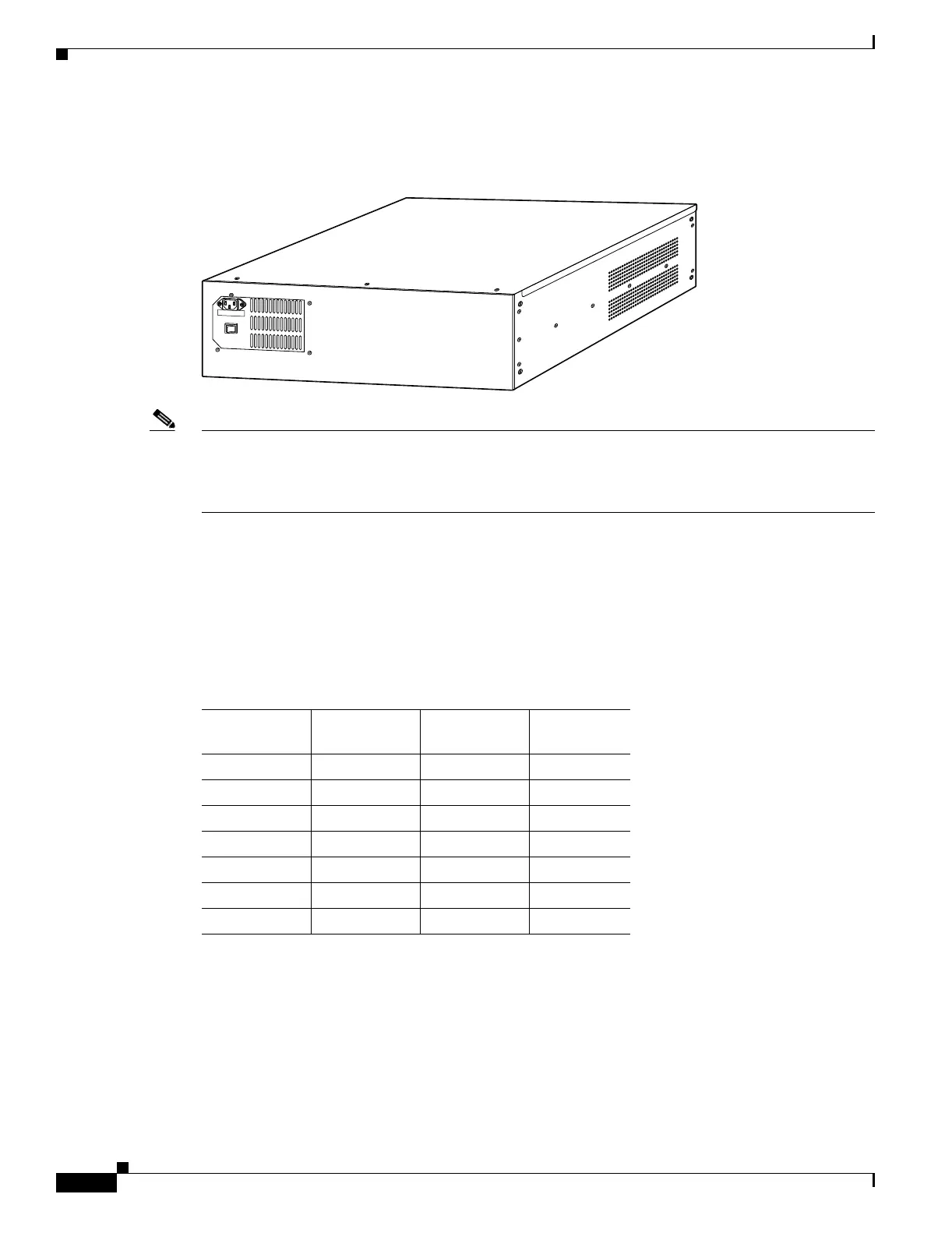
Figure 5-2 shows the rear view of the PIX 520.
Figure 5-2 PIX 520 Rear Panel
Note Use of the four-port Ethernet circuit board changes the position of the outside and inside interfaces
depending on the slot in which the circuit board is installed. Four-port Ethernet connectors are numbered
from the top connector down sequentially. On horizontally mounted cards, the slots are numbered left to
right.
The PIX 520 can be used with Ethernet circuit boards.
The four-port Ethernet circuit board provides four 10/100 Ethernet connections and has autosense
capability. Connectors on the four-port Ethernet circuit board are numbered top to bottom sequentially;
however, the actual device number depends on the slot in which the four-port Ethernet circuit board is
installed.
Table 5-1 describes how the top connector is numbered.
With the four-port Ethernet circuit board, having a circuit board in slot 3 makes the number of interfaces
greater than six; while the circuit board in slot 3 cannot be accessed, its presence does not cause
problems with the PIX security appliance.
PIX Firewall
S
E
R
IE
S
RESET
67853
Auto-Range Selection
L:90-135V H:180-270V
Table 5-1 Numbering Devices with a Four-Port Connector
Slot 0 Contains Slot 1 Contains Slot 2 Contains
Four-Port Top
Connector
4-port Any Any ethernet0
Ethernet 4-port Any ethernet1
Ethernet Ethernet 4-port ethernet2
Token Ring 4-port Any ethernet0
Token Ring Token Ring 4-port ethernet0
Token Ring Ethernet 4-port ethernet1
Ethernet Token Ring 4-port ethernet1

 Loading...


