5-5
Cisco PIX Security Appliance Hardware Installation Guide
78-15170-03
Chapter 5 PIX 520
Installing the PIX 520
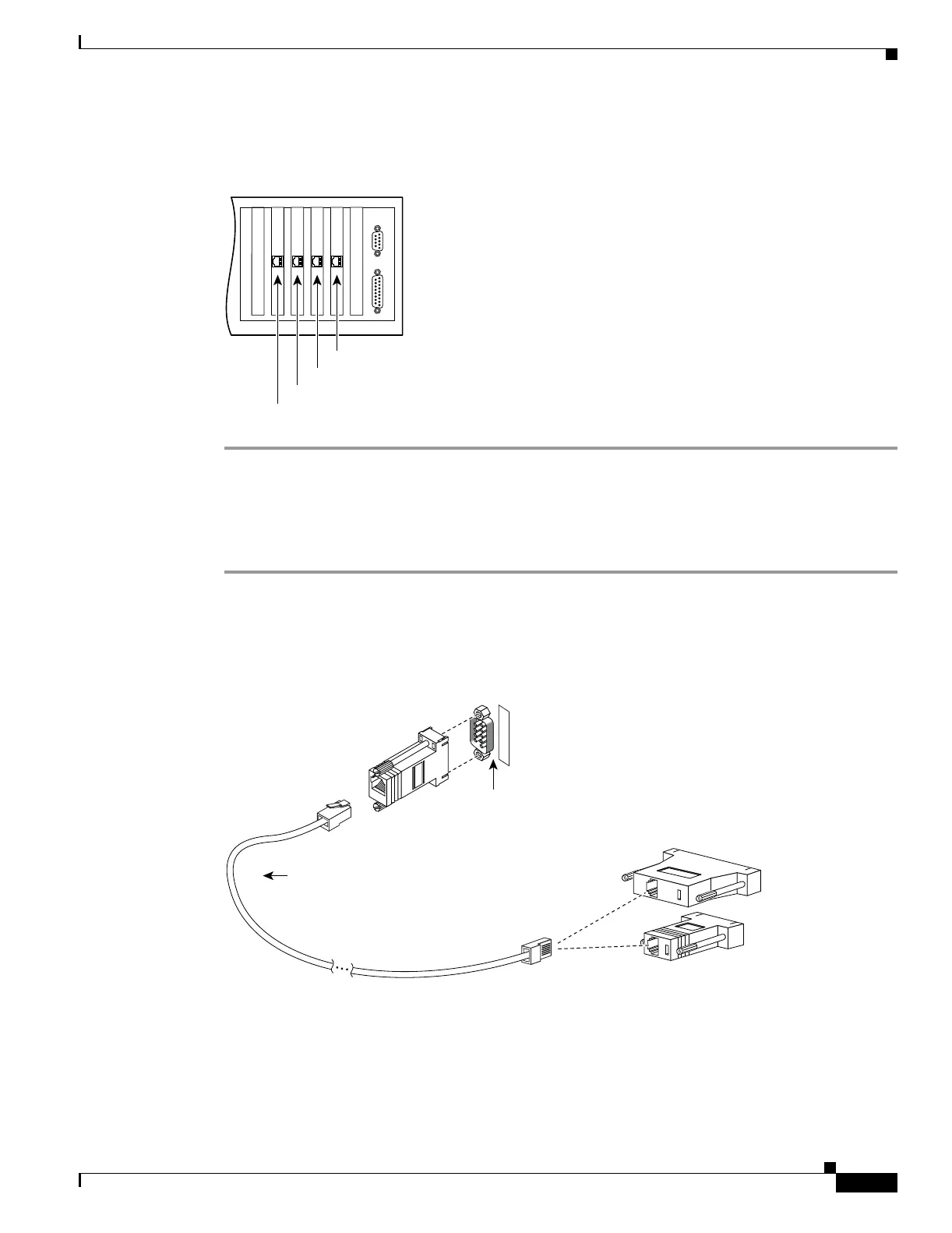
If you are not installing a four-port Ethernet circuit board, add the cables as shown in Figure 5-7.
Figure 5-7 Up to Four Single-Port Interfaces in the PIX Security Appliance
Installing Interface Cables to the PIX 520
To install interface cables to the PIX 520, perform the following steps:
Step 1 Locate the serial cable. The serial cable assembly consists of a null modem cable with RJ-45 connectors,
two separate DB-9 connectors, and a separate DB-25 connector as shown in Figure 5-8.
Step 2 Install the serial cable between the PIX security appliance and your console computer.
Figure 5-8 PIX Security Appliance Serial Cable Assembly
Step 3
Connect one of the DB-9 serial connectors to the console connector on the front panel of the PIX security
appliance.
Step 4 Connect one end of the RJ-45 null modem cable to the DB-9 connector.
Step 5 If you are installing an AC voltage PIX security appliance, connect the power cord to the power
connector on the rear panel of the PIX security appliance, and to a power outlet.
44305
Interface 1
Interface 3
Interface 2
Interface 0
DB-9-to-DB-25
serial cable
(null-modem)
Computer serial port
DB-25 or DB-9
Console
port (DB-9)
PIX security appliance
console connector
C
O
N
S
O
L
E
12275

 Loading...


