3-66
Cisco UCS C240 M4 Server Installation and Service Guide
OL-32474-01
Chapter 3 Maintaining the Server
Installing or Replacing Server Components
Installing a Version 2 930W DC Power Supply, UCSC-PSU2V2-930DC
If you are using the Version 2 930W DC power supply, you connect power using a 3-wire cable with a
keyed connector that plugs into a fixed power input socket on the power supply. See also Installing a
Version 1 930W DC Power Supply, UCSC-PSU-930WDC, page 3-67.
Caution Before beginning this wiring procedure, turn off the DC power source from your facility’s circuit breaker
to avoid electric shock hazard.
Step 1 Turn off the DC power source from your facility’s circuit breaker to avoid electric shock hazard.
Step 2 Wire the supplied 3-wire connector cable to your facility’s DC power source.
Note The supplied connector cable contains 8 AWG gauge wires. The recommended facility wire gauge is
8 AWG. The minimum facility wire gauge is 10 AWG.
Step 3 Plug the supplied connector cable into the power input socket on the power supply. The connector is
keyed to the socket so that the polarity is aligned correctly.
Step 4 Return power from your facility’s DC power source at the circuit breaker.
Step 5 See Installation Grounding, page 3-68 for additional information about chassis grounding.
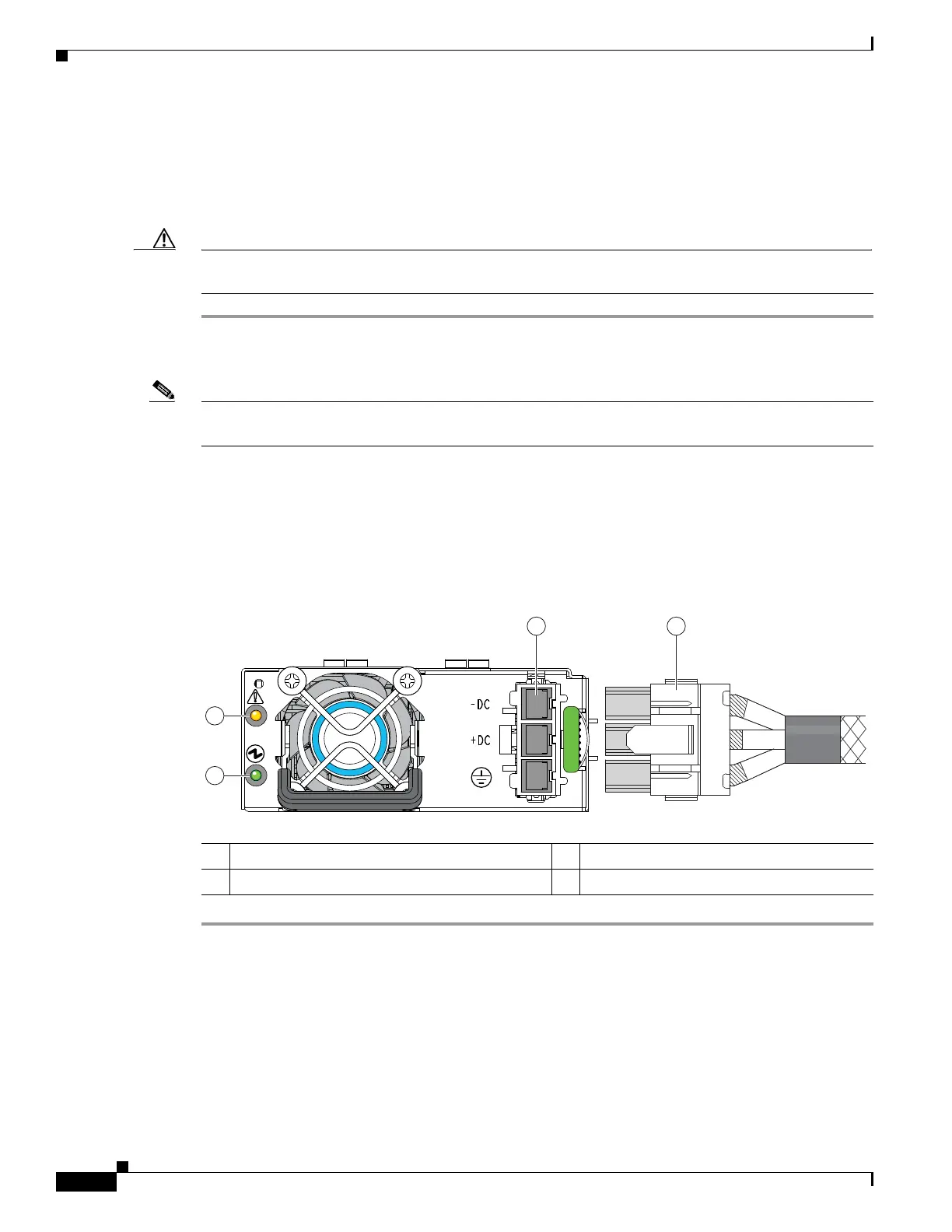
Figure 3-31 Version 2 930 W, –48 VDC Power Supply Connector Block
1 Power supply status LED 3 Fixed power input socket
2 Power supply fault LED 4 Supplied connector cable
 Loading...


