3-45
Cisco UCS C240 M4 Server Installation and Service Guide
OL-32474-01
Chapter 3 Maintaining the Server
Installing or Replacing Server Components
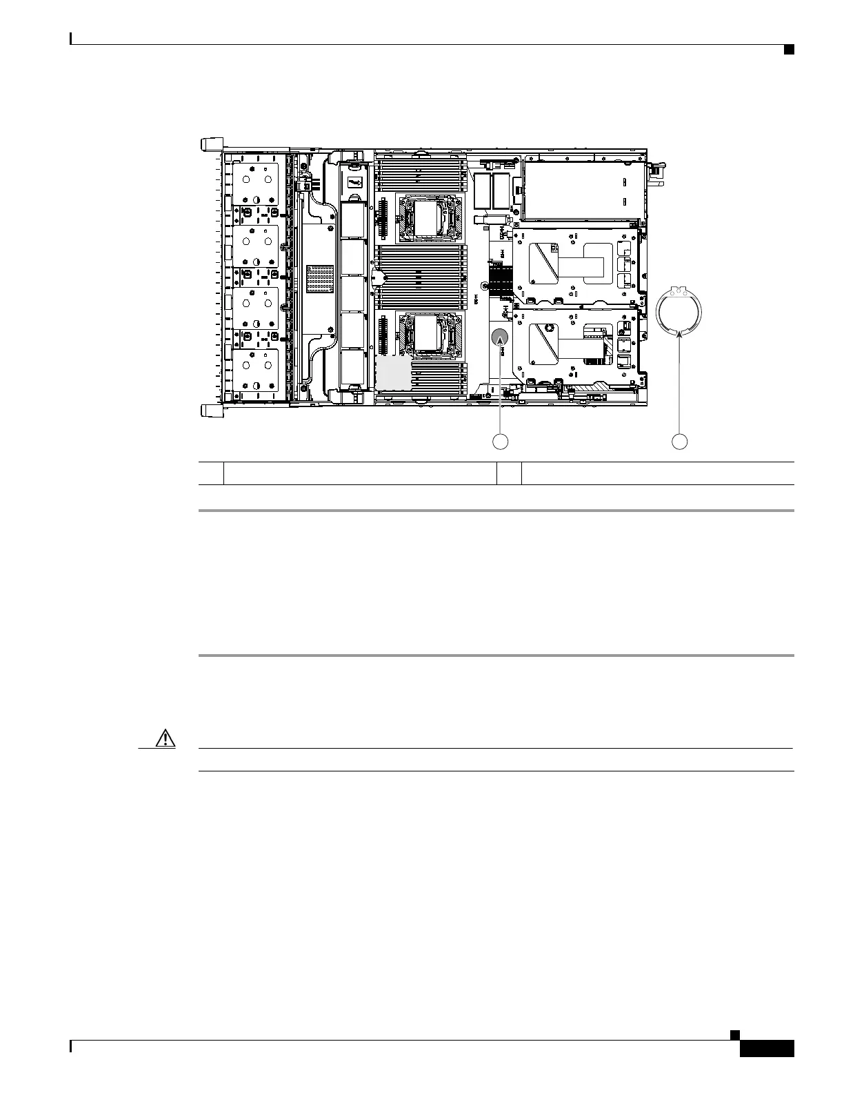
Figure 3-24 RTC Battery Location and Prying Point
Replacing an Internal SD Card
The server has two internal SD card bays on the motherboard.
Dual SD cards are supported. RAID 1 support can be configured through the Cisco IMC interface.
Step 1 Power off the server as described in Shutting Down and Powering Off the Server, page 3-9.
Step 2 Slide the server out the front of the rack far enough so that you can remove the top cover. You might have
to detach cables from the rear panel to provide clearance.
Caution If you cannot safely view and access the component, remove the server from the rack.
Step 3 Remove the top cover as described in Removing and Replacing the Server Top Cover, page 3-10.
Step 4 Remove an SD card (see Figure 3-25).
a. Push on the top of the SD card, and then release it to allow it to spring out from the slot.
b. Remove the SD card from the slot.
Step 5 Install an SD card:
a. Insert the SD card into the slot with the label side facing up.
b. Press on the top of the card until it clicks in the slot and stays in place.
Step 6 Replace the top cover.
Step 7 Replace the server in the rack, replace cables, and then power on the server by pressing the Power button.
1 RTC battery holder on motherboard 2 Prying point
352964
FAN 05
FAN 04
FAN 0 3
FAN 02
FAN 01
CPU 1
CPU 2
SD1
SD2
Riser 2
Riser 1
1 2
 Loading...


