2-80
Cisco XR 12000 Series Router SIP and SPA Hardware Installation Guide
OL-17438-04
Chapter 2 Overview: Cisco XR 12000 Series Router Shared Port Adapters
24-Port Channelized T1/E1/J1 ATM CEoP SPA Overview
RJ-45 Cable Pinouts
T1 lines from individual subscribers are attached to RJ-45 connectors on the front of the 24-port patch
panel. Each RJ-45 port accommodates an individual T1 subscriber line.
Pins 1 and 2 and 4 and 5 of the RJ-45 connectors are used for the 24-port CEoP SPA’s Transmit (TX)
and Receive (RX) signals. Depending on how the cable is installed between the SPA and its patch panel
(rear), the RJ-45 connectors operate as follows:
• If the TX cable lead is connected to Transmit on the patch panel and RX is connected to Receive:
–
The SPA’s TX signals are transmitted on RJ-45 pins 1 (ring) and 2 (tip).
–
The SPA’s RX signals are received on RJ-45 pins 4 (ring) and 5 (tip).
• If the TX cable lead is connected to Receive on the patch panel and RX is connected to Transmit:
–
RJ-45 pins 1 and 2 are used for the SPA’s RX signal.
–
RJ-45 pins 4 and 5 are used for the SPA’s TX signal.
Patch Panel Cabling
If you are connecting two 24-Port Channelized T1/E1/J1 ATM CEoP SPAs to each other, you must cable
both SPA’s patch panels together using a T1 cross-over cable or a T1 straight-through cable. The type of
cable you use (cross-over or straight-through) depends on how the CEoP SPAs are cabled to their patch
panels:
• If both CEoP SPAs are connected to their patch panels in the same manner (TX to Transmit and
RX to Receive, or TX to Receive and RX to Transmit), use a T1 cross-over cable to connect the
patch panels to each other.
• If both CEoP SPAs are connected to their patch panels in a different configuration (TX to Transmit
and RX to Receive on one SPA, and TX to Receive and RX to Transmit on the other SPA), use a
T1 straight-through cable (standard RJ-45 patch cable) between the patch panels.
24-Port Channelized T1/E1/J1 ATM CEoP SPA Patch Panel
The recommended patch panel is part number DCC2484/25T1S from SMP Data Communications
(http://www.smpdata.com).
To order the patch panel, contact the Sales and Marketing Support staff at SMP Data Communications:
• 800-880-7674 (toll free in the U.S.A.)
• 828-298-2260 (outside the U.S.A.)
• ciscoinfo@smpdata.com (email)
Line 24 TX Tip
TX Ring
25
75
24
49
Not connected
RX Tip
RX Ring
49
99
Not connected 24
49
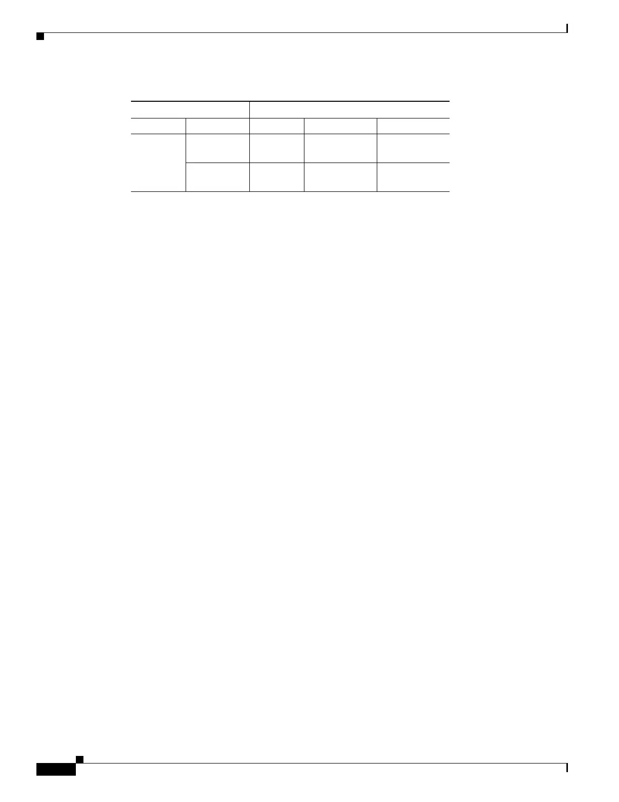
Table 2-49 24-Port Channelized T1/E1/J1 ATM CEoP SPA Cable Connector Pinouts (continued)
Subscriber Connector Pins
Line Signal SPA TX Cable Lead RX Cable Lead
 Loading...