2-32
Cisco XR 12000 Series Router SIP and SPA Hardware Installation Guide
OL-17438-04
Chapter 2 Overview: Cisco XR 12000 Series Router Shared Port Adapters
1-Port Channelized STM-4/OC-12 SPA Overview
• 1-Port Channelized STM-4/OC-12 SPA Interface Specifications, page 2-33
• 1-Port Channelized STM-4/OC-12 SPA Cables and Connectors, page 2-33
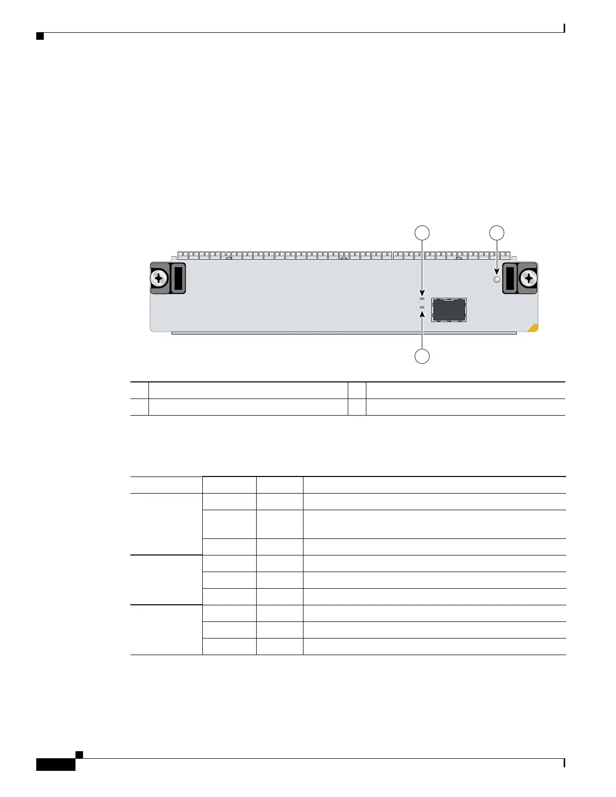
1-Port Channelized STM-4/OC-12 SPA LEDs
The 1-Port Channelized STM-4/OC-12 SPA has two types of LEDs: an A/L LED for each port and a
STATUS LED, as shown in Figure 2-19.
Figure 2-19 1-Port Channelized STM-4/OC-12 SPA Faceplate
The 1-Port Channelized STM-4/OC-12 SPALEDs are described in Table 2-28.
1 C/A (Carrier/Alarm) LED 3 STATUS LED
2 A/L (Active Loopback) LED
S
UTA
T
S
A/C
L
/
A
280921
SPA-1XCHOC12/DS0
3
1 2
Table 2-28 1-Port Channelized STM-4/OC-12 SPA LEDs
LED Label Color State Meaning
C/A Off Off Port is not enabled by software.
Green On Port is enabled by software, and there is a valid T3 signal
without any alarms.
Amber On Port is enabled by software, and there is at least one alarm.
A/L Off Off Port is not enabled by software.
Green On Port is enabled by software, loopback is off.
Amber On Port is enabled by software, loopback is on.
STATUS Off Off SPA power is off.
Green On SPA is ready and operational.
Amber On SPA power is on and good, and SPA is being configured.
 Loading...