2-8
Cisco XR 12000 Series Router SIP and SPA Hardware Installation Guide
OL-17438-04
Chapter 2 Overview: Cisco XR 12000 Series Router Shared Port Adapters
8-Port Channelized T1/E1 SPA Overview
Packet data is transported with a user-configurable encapsulation (such as Point-to-Point Protocol [PPP]
or High-Level Data Link Control [HDLC]), and is mapped to T3 and E3 frames. The encapsulations add
transport overhead to the packet of data frames before transporting, and are stripped when a packet is
transported to the far end.
The T3/E3 SPA interface is compliant with ANSI and Telco standards. The interface also provides
support for Management Information Base (MIB) RFC 2495, RFC 2496, and T1.231.
Note The 2-Port and 4-Port Channelized T3 SPA supports Frame Relay Fragmentation (FRF.12) and Multilink
Fame Relay (MFR) features for Cisco IOS XR Software Release 3.6.0 and later releases.
2-Port and 4-Port Channelized T3 SPA Cables and Connectors
The interface connectors on the 2-Port and 4-Port Channelized T3 SPA are 75-ohm coaxial Siemax
types, with one connector and cable for transmit (TX) and one for receive (RX).
The following cables can be used with the 2-Port and 4-Port Channelized T3 SPA. The cables have BNC
connectors on one end and the Siemax connectors on the other.
• CAB-T3E3-RF-BNC-M (T3 or E3 Cable, 1.0/2.3 RF to BNC-Male, 10 feet)
• CAB-T3E3-RF-BNC-F (T3 or E3 Cable, 1.0/2.3 RF to BNC-Female, 10 feet)
• CAB-T3E3-RF-OPEN (T3 or E3 Cable, 1.0/2.3 RF to BNC-Open end, 10 feet)
Note The Cisco cable part numbers are 72-4124-01 (with Male BNC end) and 72-4131-01 (with Female BNC
end).
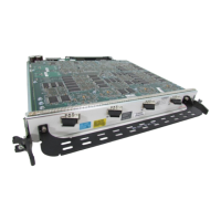
Figure 2-2 shows the Siemax connectors on the 2-Port and 4-Port Channelized T3 SPA, and Table 2-6
provides the signal descriptions for these connectors.
8-Port Channelized T1/E1 SPA Overview
The following sections describe the 8-Port Channelized T1/E1 SPA:
• 8-Port Channelized T1/E1 SPA LEDs, page 2-9
• XFP Connections, page 2-14
• 8-Port Channelized T1/E1 SPA Cables, Connectors, and Pinouts, page 2-10
Table 2-6 2-Port and 4-Port Channelized T3 SPA Connectors
Connector Label Meaning
TX Transmitted signals appear on the center contact, and the outer shield is ground
for the 75-ohm RG-59 coaxial cable you attach to the TX BNC Siemax connector.
RX Received signals appear on the center contact, and the outer shield is ground for
the 75-ohm RG-59 coaxial cable you attach to the RX BNC Siemax connector.
 Loading...


