2-9
Cisco XR 12000 Series Router SIP and SPA Hardware Installation Guide
OL-17438-04
Chapter 2 Overview: Cisco XR 12000 Series Router Shared Port Adapters
8-Port Channelized T1/E1 SPA Overview
8-Port Channelized T1/E1 SPA LEDs
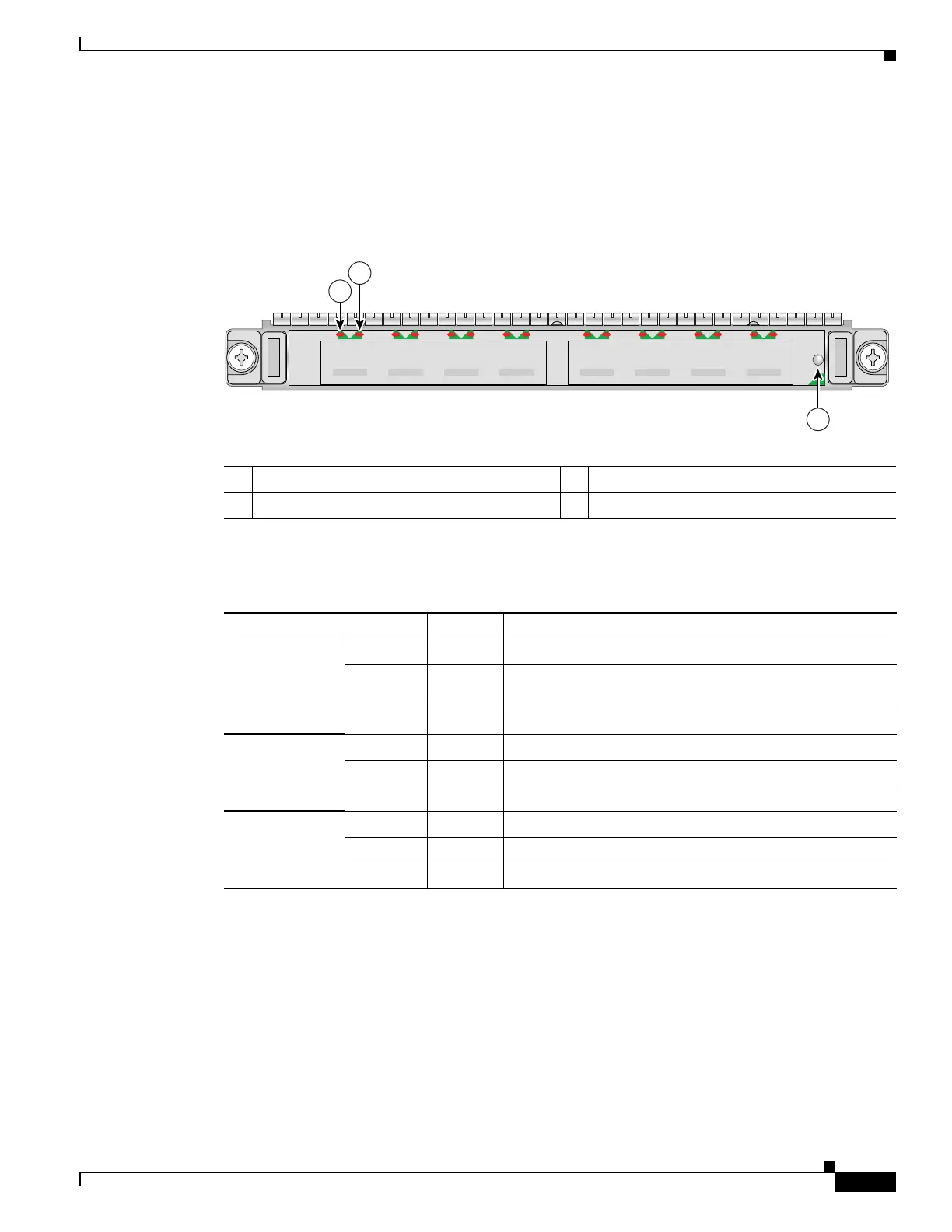
The 8-Port Channelized T1/E1 SPA has three types of LEDs. There are two LEDs for each port on the
SPA, and one STATUS LED as shown in Figure 2-3.
Figure 2-3 8-Port Channelized T1/E1 SPA Faceplate
The 8-Port Channelized T1/E1 SPA LEDs are described in Table 2-7.
8-Port Channelized T1/E1 SPA Interface Specifications
The E1 interface on the 8-Port Channelized T1/E1 SPA uses RJ-48c receptacles for E1 (120-Ohm) cables
with RJ-45 connectors. You can use all ports simultaneously. Each E1 connection supports interfaces that
meet G.703 standards. The RJ-45 connection does not require an external transceiver. The E1 ports are
E1 interfaces that use 120-ohm shielded twisted pair (STP) cables.
1 C/A (Carrier/Alarm) LED 3 STATUS LED
2 A/L (Active Loopback) LED
STATUS
3
116852
SPA-8XCHT1/E1
C/A A/L
0
C/A
3
A/L A/L A/LC/A
2
C/A
1
C/A A/L
4
C/A
7
A/L A/L A/LC/A
6
C/A
5
1
2
Table 2-7 8-Port Channelized T1/E1 SPA LEDs
LED Label Color State Meaning
C/A Off Off Port is not enabled by software.
Green On Port is enabled by software, and there is a valid T1 or E1
signal without any alarms.
Amber On Port is enabled by software, and there is at least one alarm.
A/L Off Off Port is not enabled by software.
Green On Port is enabled by software, loopback is off.
Amber On Port is enabled by software, loopback is on.
STATUS Off Off SPA power is off.
Amber On SPA power is on and good, and SPA is being configured.
Green On SPA is ready and operational.
 Loading...