1-13
Cisco XR 12000 Series Router SIP and SPA Hardware Installation Guide
OL-17438-04
Chapter 1 Overview: Cisco XR 12000 Series Router SPA Interface Processors
Cisco XR 12000 SIP-501 Overview
SPA Interface Addresses on the Cisco XR 12000 SIP-501
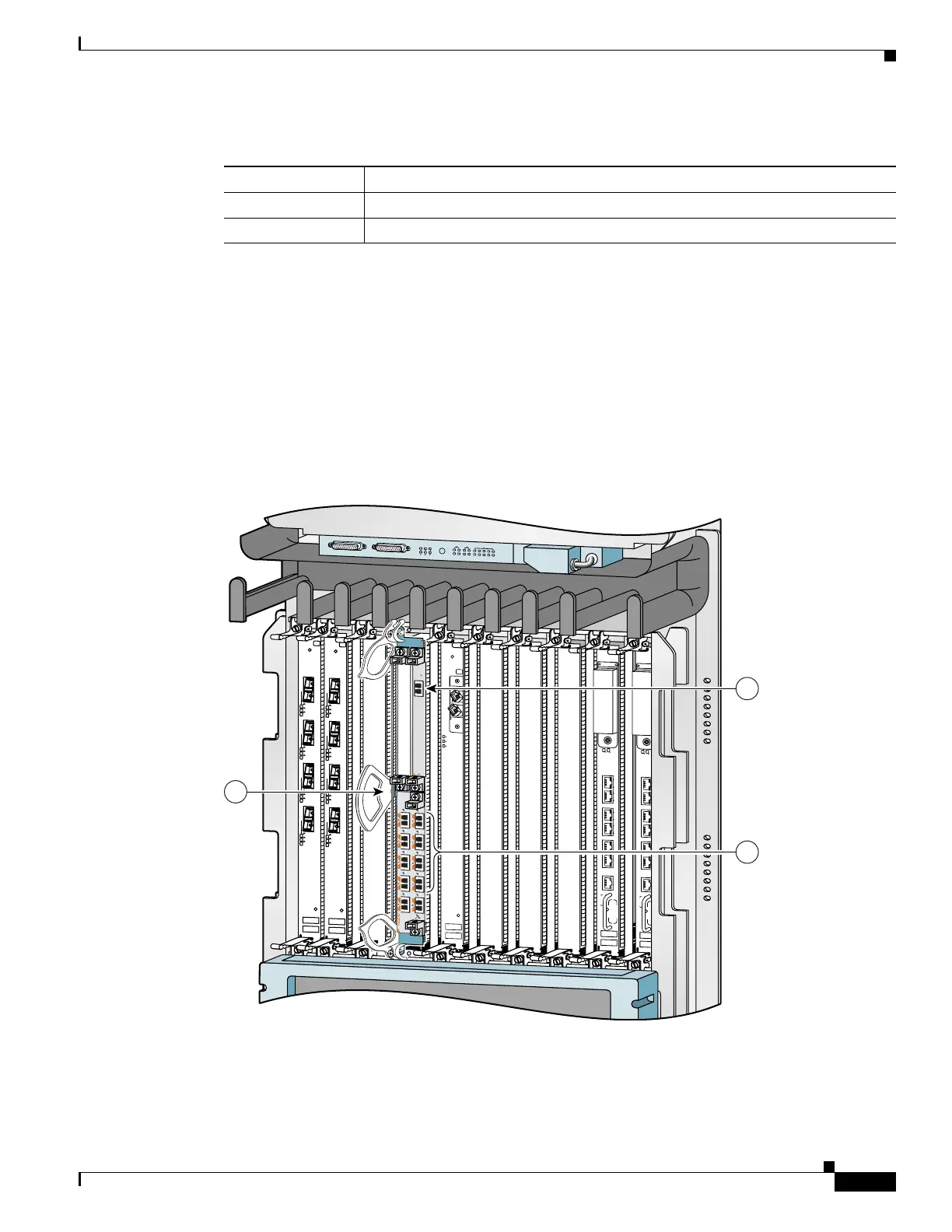
A Cisco 12000 Series Router identifies a SPA interface address by its SIP slot number, SPA subslot, and
port number on the SPA, in the format slot/subslot/port. Subslots and ports are numbered starting from
0, so each Cisco XR 12000 SIP-601 has two subslots 0 (left) and 1 (right). For example, the interface
address of a 1-port SPA located in the second SIP subslot, where the SIP is inserted into router line card
slot 3 is 3/1/0. Figure 1-12 shows the slot, subslot, and port locations for the 1-Port 10-Gigabit Ethernet
SPA and the 10-Port Gigabit Ethernet SPA.
Figure 1-12 Slot, Subslot, and Port Locations for the 1-Port 10-Gigabit Ethernet SPA and the
10-Port Gigabit Ethernet SPA.
Table 1-12 Subslot Locations for the 1-Port 10-Gigabit Ethernet SPA
Call Out Number Description
1 Subslot 0
2 Subslot 1
ACTIVE
0
CARRIER
RX PKT
ACTIVE
1
CARRIER
RX PKT
ACTIVE
2
CAR
RIER
RX PKT
ACTIVE
3
CARRIER
RX PKT
Q OC-3/STM-POS
ACTIVE
0
C
ARRIER
RX PKT
ACTIVE
1
CARRIER
RX PKT
ACTIVE
2
CAR
RIER
RX PKT
AC
TIVE
3
CARRIER
RX PKT
Q OC-3/STM-POS
A
C
T
IV
E
C
A
R
R
IE
R
R
X
P
K
T
OC-48/STM-16-SCPOS
E
JE
C
T
ACT
SIG
ACT
SIG
SLOT-1
SLOT-0
CONSOLE ETH 2AUX
R
E
S
E
T
PERFORMANCE ROUTE PROCESSOR 2
BITS 1BITS 0
DATA
LINK
DATA
LINK
ETH 1ETH 0
E
J
E
C
T
ACT
SIG
ACT
SIG
SLOT-1
SLOT-0
CONSOLE ETH 2AUX
R
E
S
E
T
PERFORMANCE ROUTE PROCESSOR 2
BITS 1BITS 0
DATA
LINK
DATA
LINK
ETH 1ETH 0
ALARM A
ALARM B
A
A
M
BUS
M
INO
R
B
FAIL
ENABLE
M
AJOR
C
RITIC
AL
B
0
CSC
1
0
SFC
1
2
3
4
129009
S
T
A
T
U
S
ACTIVE/LINK
SPA-1XTENGE-XFP-A
1
2
3
 Loading...