IGS-NT Communication Guide
109
!)
Response: 01 03 FA 00 00 00 00 00 00 00 20 00 … 00 00 F4 01 FD 00 FD 00 FD 00 00 00 00 00 00 00
00 64 20 00 00 00 00 64 00 D8 00 55 01 00 00 A1 00 7A 00 64 00 0A 00 18 00 00 00 00 … 00 00 20 3B
01 = Controller address
03
= Modbus function code (Read Multiple Registers
(page 133))
FA = Length of read data in Bytes (in HEX)
00 .. 00
= Object data value > for reading this data see table 7
History Record in Communication object
description (in PC tool -> File –> Generate Cfg Image
–> Generate Cfg Image (Comm. Objects …))
3B 20 = Check field calculation (page 143)
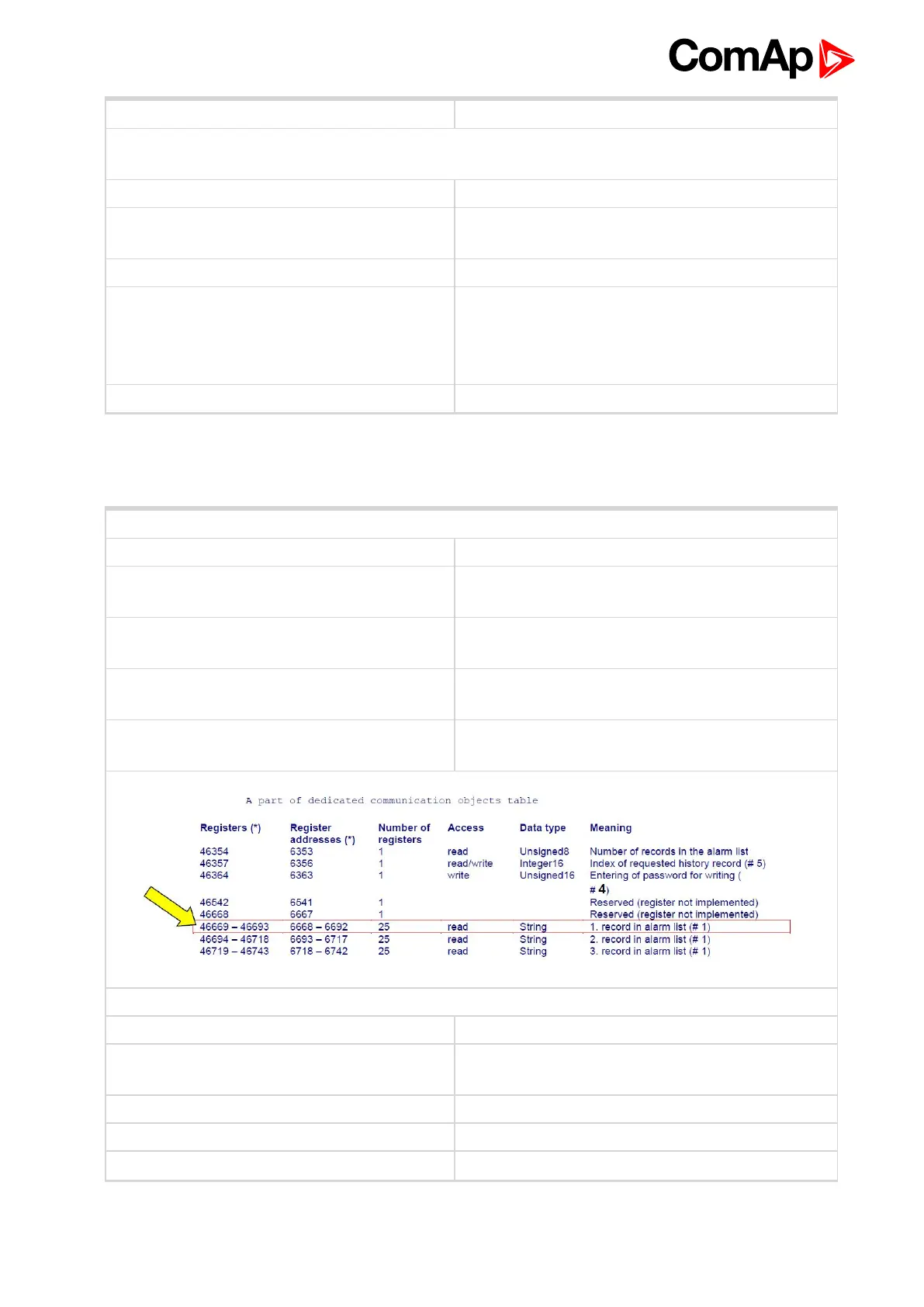
7.4.18 AlarmList reading
For more information see Alarm list reading on page 139.
Request: 01 03 1A 0C 00 19 43 B1
01 = Controller address
03
= Modbus function code (Read Multiple Registers
(page 133))
1A 0C
= Register address: Register number (46669) – 40001 =
6668 DEC => 1A0C HEX
00 19
= Number of registers > 46669 – 46693 => 25 DEC =>
19 HEX
B1 43
= Check field calculation (page 143) (write LSB MSB
!)
Response: 01 03 32 2A 53 64 20 53 44 20 31 32 … 00 00 18 F5
01 = Controller address
03
= Modbus function code (Read Multiple Registers
(page 133))
32 = Length of read data in Bytes (in HEX)
2A 53 = Object data value (* S)
64 20 = Object data value (d _)
 Loading...