IGS-NT Communication Guide
63
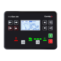
5.1.2 InteliVision 8 display
Controllers
Controllers IG-NT-BB IS-NTC-BB IM-NT-BB IG-NTC-BB IM-NTC-BB
Connectionapplicable YES YES YES YES YES
Physical port
RS485 (1),
CAN(2)
RS485 (1),
CAN(2)
RS485 (1),
CAN(2)
RS485 (1),
CAN(2)
RS485 (1),
CAN(2)
More info IG/IM-NT-BB - Terminal (page 17)
IG/IS/IM-NTC-BB -
Terminals (page 13)
Controllers IG-NT IM-NT IG-NTC IS-NT-BB
Connectionapplicable YES YES YES YES
Physical port
RS485 (1),
CAN(2)
RS485 (1),
CAN(2)
RS485 (1),
CAN(2)
RS485 (1),
CAN(2)
More info IG/IM-NT-BB - Terminal (page 17)
IG/IS/IM-NTC-BB - Terminals (page
13)
It is possible to connect up to 3 IV8 displays to RS485(1) terminal Link (see IG/IS/IM-NTC-BB - Terminals on
page 13) and up to 2 displays on CAN(2) bus.
Note: Connection InteliVision8 to IG/IS-NT controllers is described in InteliVision8 Global Guide.
Note: In case of connection IV8 to controller via CAN(2) bus the collision can occur. IV8 is in this case
connected via 123 and 124 CAN (2) physical address, that can be used for other peripheral modules (see the
table bellow). Make sure, that real CAN(2) physical address (123 and 124) are not shared by other devices such
as I-LB+ module.
Real
CAN2
Address
IG-MU
I-LB
(local)
(RS232/485)
I-LB
(modem)
I-LB+
(USB)
IG-IB
(IBConfig<1,5)
IG-IB
(IBConfig>1,6)
IV-
Display
I-RD
-CAN
122 - - addr.2 - - - - -
123 addr.2 addr.2 - addr.1 addr.1 addr.2 addr.2 addr.2
124 addr.1 addr.1 - addr.2 addr.2 addr.1 addr.1 addr.1
125 modem - addr.1 - - - - -
Controller setup
(Setpoints/Comms settings group)
RS485(1) conv. = DISABLED

 Loading...


