ground clamp or any grounded piece of
metal. IMPORTANT! The welding wire is car-
rying welding current whenever the welder is
turned on.
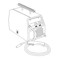
11. Pull the trigger on the welding gun to feed
the wire through the gun assembly.
12. When at least an inch of wire sticks out
past the end of the gun, release the trigger.
13. Install the supplied 0.030 inch (0.8mm)
size contact tip.
Note: Due to inherent variances in flux-
cored welding wire, it may be necessary
to use a welding tip one size larger than
your flux-core wire if jams occur.
14. Slide the contact tip over the wire
(protruding from the end of the gun).
Screw the contact tip into the end of the
gun and hand tighten securely.
15. Install the nozzle on the gun assembly.
16. Cut off the excess wire that extends past
the end of the nozzle.
ARC RAYS CAN INJURE EYES!
To reduce the risk of arc flash, make certain
that the wire coming out of the end of the
gun does not come in contact with the
ground clamp or any grounded material dur-
ing the drive tension setting process.
17. Set the wire drive tension.
a. Pull the trigger on the gun.
b. Turn the drive tension adjustment
knob clockwise, increasing the drive
tension until the wire seems to feed
smoothly without slipping.
Note: If TOO MUCH tension is applied, the
wire will slip on the drive roller or will not be
able to feed at all. If TOO LITTLE tension is
applied, the spool of wire will want to
unspool itself.
When the drive tension is set correctly, there
should be no slippage between the wire and
the drive roller. But if an obstruction occurs
along the wire feed path, the wire should
then slip on the drive roller.
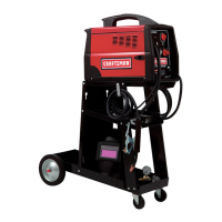
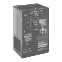
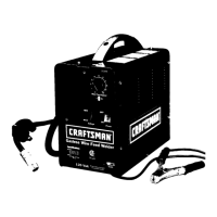
Your new MIG (Metal Inert Gas) Wire Feed
welder is designed for maintenance and
sheet metal fabrication. The welder consists
of a single-phase power transformer, and a
unique built-in control/feeder. This welder is
capable of welding with 0.030 inch
self-shielding flux-core wire.
Now you can weld 18 gauge sheet metal up
to 3/16 inch with a single pass. You can weld
1/4 inch steel with beveling and multiple pass
techniques. Table 2 lists your wire feed
welder specifications.
Table 2. Welder Specifications
Primary (input) volts 120 Vac
Welding Range 60-120 Amps
Primary (inputs) Amps 20
Phase Single
Frequency 60 Hz
Secondary (output) volts 17
Secondary (output) amps 80
Duty Cycle Rating at 80 amps 20%
Open Circuit Volts/Max.! 25 Vac
DUTY CYCLE
The duty cycle rating of a welder defines how
long the operator can weld and how long the
welder must be rested and cooled. Duty cycle
is expressed as a percentage of 10 minutes
and represents the maximum welding time
allowed. The balance of the 10 minute cycle is
required for cooling.
Your new welder has a duty cycle rating of
20% at the CSA rated output of 80 amps. This
means that you can weld for two (2) minutes
out of 10 with the remaining eight (8) minutes
required for cooling. (See Table 3.)
Table 3. Duty Cycle Ratings
Duty Maximum Required
Cycle Welding Resting
Rating Time Time
20% 2 minutes 8 minutes
40% 4 minutes 6 minutes
60% 6 minutes 4 minutes
80% 8 minutes 2 minutes
100% 10 minutes 0 minutes
11
 Loading...