DO GUIDE
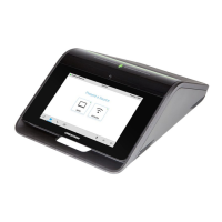
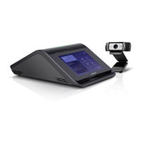
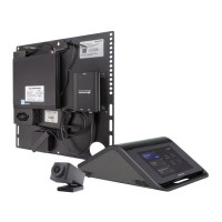
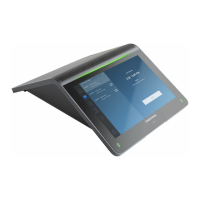
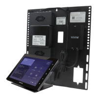
CCS-UC-1
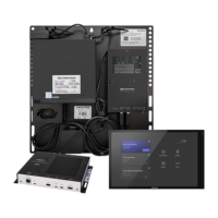
Crestron Mercury™ Tabletop Conference System
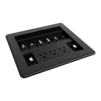
DO Install the Cable Retention Plate
Install the cable retention plate as shown in the following diagram. The cable retention plate is designed to t at the cable exit location at the rear of the
Crestron Mercury chassis and provides three tie-down points for cables connected to the device.
NOTE: If the CCS-UCA-SMK swivel mount kit is to be used, use the cable retention bracket included with the CCS-UCA-SMK. For details, refer to the
CCS-UCA-SMK DO Guide (Doc. 7882) at www.crestron.com/manuals.
CAUTION: When turning over the device, place the device on a soft surface to avoid damage to the unit.
NOTE: Allow the cable retention plate adhesive to properly cure before attaching any wiring.
DO Connect the Device
The Crestron Mercury device should be wired for its intended use. Refer to the following table to determine what is necessary for the specic installation.
Feed Cables Through the Swivel Tube Plate (Installations with CCS-UCA-SMK only)
If the CCS-UCA-SMK swivel mount kit is used in the installation, refer to the CCS-UCA-SMK DO Guide (Doc. 7882) at www.crestron.com/manuals.
NOTE: If the 6' HDMI input cable and the 6' USB cable are to be routed to the front of the Crestron Mercury device, do not route the cables through the
swivel tube plate.
Hardware Hookup
When wiring the Crestron Mercury device to external devices, it is highly recommended to use the cables that ship with the Crestron Mercury
device. Each kit ships with every cable needed for most rooms. The cables and accessories have been designed so that a service loop can be
implemented prior to the cables leaving the Mercury’s chassis body (if necessary). If an extension option is required, Crestron solutions should
always be used and can be found under the MODELS & ACCESSORIES tab at www.crestron.com/products/model/CCS-UC-1.
DO Check the Box
QUANTITY PRODUCT PART NUMBER
1 Cable, RJ-45 Male - RJ-45 Male, 12' (3.66 m) 2033988
1 Cable, USB 2.0, A - micro B, 6’ (1.83 m) 2047803
1 Retention Plate, Cable 2047908
3 Tie Wrap 2047935
CCS-UC-1 W/PS KIT Only
1 Power Pack, PW-2420RU 6500187
CCS-UC-1-AV W/PS KIT Only
1 Cable, HDMI, 6' (1.83 m), Thin 6508218
1 Cable, HDMI, 20' (6.10 m) 6503567
1 Cable, USB 2.0, A Female - A, 15’ (4.57 m) 6508260
1 Camera, CCS-CAM-USB-F-100 6506442
1 IR Emitter Probe, STIRP 6500940
1 Power Pack, PW-2420RU 6500187
Install cable
retention
plate here
Cable retention
plate installed
REQUIRED WIRING
SCENARIO
GENERAL
WIRING
WIRING WITH SMK ZOOM ROOM
Route cables through swivel tube plate No Yes Optional
Service Loops Yes No Yes
Cable Retention Plate Yes Yes Yes
AUX:
10BASE-T/100BASE-TX
Ethernet to SIP or AirMedia
®
router
CCS-UCA-MIC Microphone pods
(sold separately)
Must connect AC power pack to CCS-UC-1
Laptop
via included USB cable and 6' (1.83 m) and HDMI cable
(CCS-UC-1-AV W/PS KIT only)
Display device
via 20' (6.10 m) HDMI
®
cable and IR or serial control
(CCS-UC-1-AV W/PS KIT only)
USB/ACC:
For future use
Ground
CCS-CAM-USB-F-100
(
CCS-UC-1-AV W/PS KIT
only)
100-240 V
50/60 Hz:
From ac power outlet
24 Vdc, 2.5 A
AC power pack
(CCS-UC-1 W/PS KIT and
CCS-UC-1-AV W/PS KIT only)
Corporate
network
or PoE+
LAN
100-240 V
50/60 Hz:
From ac power outlet
24 Vdc, 2.5 A
AC power pack
(CCS-UC-1 W/PS KIT and
CCS-UC-1-AV W/PS KIT only)
CCS-UCA-MIC Microphone pods
(sold separately)
Must connect AC power pack to CCS-UC-1
USB B
To USB port on Zoom room
PC via included USB cable
USB/ACC
Insert included USB stick
here.
Ground
LAN