SiUS122226E Check
Part 6 Service Diagnosis 231
8.8 Outdoor Fan Motor Check
Check No.16 2/3/4MXS, 2/3MXL(H)
Make sure that the voltage of 320 ± 30 V is applied.
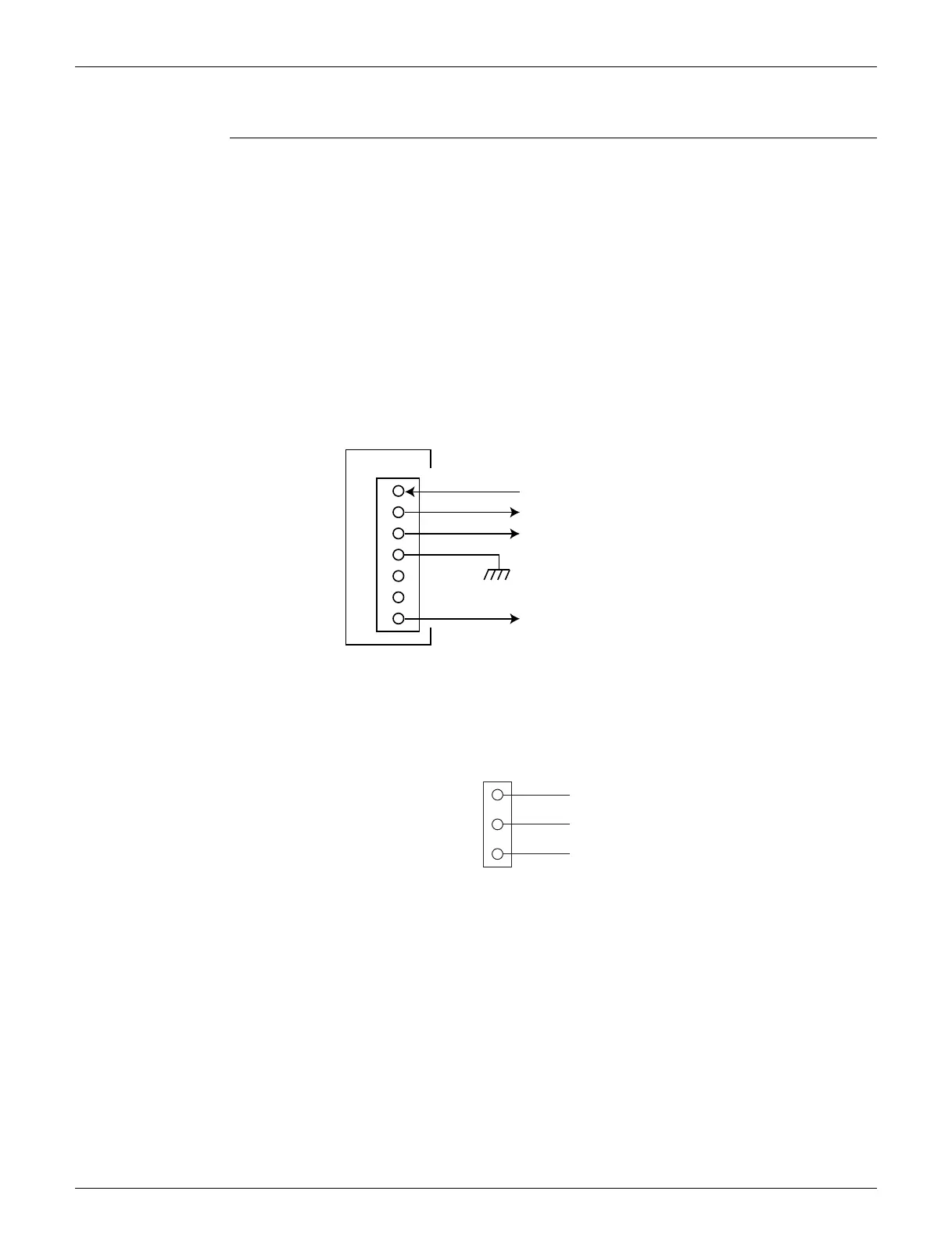
1. Set operation OFF and power OFF. Disconnect the connector S70.
2. Check that the voltage between the pins 4 - 7 is 320 VDC.
3. Check that the control voltage between the pins 3 - 4 is 15 VDC.
4. Check that the rotation command voltage between the pins 2 - 4 is 0 ~ 6.5 VDC.
5. Keep operation OFF and power OFF. Connect the connector S70.
6. Check whether 4 pulses (0 ~ 15 VDC) are output at the pins 1 - 4 when the fan motor is rotated
1 turn by hand.
When the fuse is melted, check the outdoor fan motor for proper function.
If NG in step 2 Defective PCB Replace the outdoor unit PCB (main PCB).
If NG in step 4 Defective Hall IC Replace the outdoor fan motor.
If OK in both steps 2 and 4 Replace the outdoor unit PCB (main PCB).
5MXS, 4MXL(H)
Manually rotate the outdoor fan motor and check if 4 pulses of sinusoidal voltage are detected
between pins 1-2 and then pins 2-3.
R6000524
1
2
3
4
5
6
7
320 VDC
(R19655)
S70
PCB
Actual rotation pulse input (0 ~ 15 VDC)
Rotation command voltage (0 ~ 6.5 VDC)
Control voltage 15 VDC
3
2
1
U (red)
S70
V (white)
W (black)
 Loading...