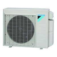
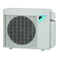
Outdoor Unit SiUS122226E
44 Part 3 Printed Circuit Board Connector Wiring Diagram
6. Outdoor Unit
6.1 2/3/4MXS-WMVJU9, 2/3MXL-WMVJU9, 2/3MXLH-WVJU9
Main PCB (PCB1)
1) S Connector for terminal block (indoor - outdoor transmission)
2) S15 Connector for COOL/HEAT lock
Refer to page 269 for details.
3) S20 (white) Connector for electronic expansion valve coil A port
4) S21 (red) Connector for electronic expansion valve coil B port
5) S22 (blue) Connector for electronic expansion valve coil C port (24/36 class)
6) S23 (yellow) Connector for electronic expansion valve coil D port (36 class)
7) S40 Connector for overload protector and high pressure switch
8) S70 Connector for DC fan motor
9) S80 Connector for four way valve coil
10) S90 Connector for thermistors
(outdoor temperature, outdoor heat exchanger, discharge pipe)
11) S92 Connector for gas pipe thermistor
12) S93 Connector for liquid pipe thermistor
13) S201, S202 Connector for service monitor PCB (PCB2)
14) HL1, HN1 Wire harness for terminal strip (power supply)
15) E1, E2 Wire harness for ground wire
16) DP1, DP2 Wire harness for drain pan heater (MXLH-W only)
17) U, V, W Wire harness for compressor
18) FU1, FU2 Fuse (3.15 A, 250 V)
19) FU3 Fuse (30 A, 250 V)
20) V2, V3, V401 Varistor

 Loading...


