Outdoor Unit SiUS122226E
46 Part 3 Printed Circuit Board Connector Wiring Diagram
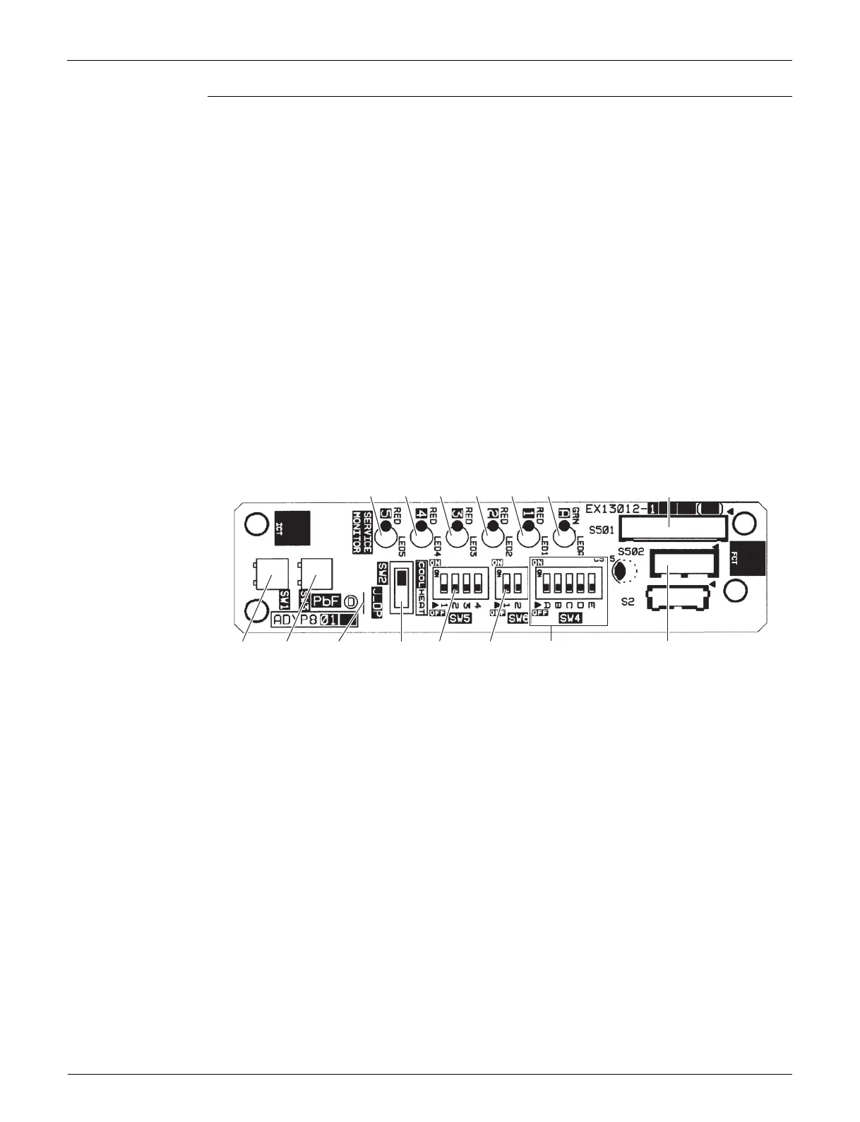
Service Monitor
PCB (PCB2)
SW5-1, SW5-3, SW5-4 and SW6-2 have no function. Keep them OFF.
1) S501, S502 Connector for main PCB (PCB1)
2) LED A LED for service monitor (green)
3) LED1, LED2,
LED3, LED4,
LED5
LED for service monitor (red)
4) SW1 Forced cooling operation ON/OFF switch
Refer to page 241 for details.
5) SW2 Operation mode switch
Refer to page 241 for details.
6) SW3 Wiring error check switch
Refer to page 243 for details.
7) SW4 Priority room setting switch
Refer to page 268 for details.
8) SW5-2 Warmer airflow setting switch
Refer to page 272 for details.
9) SW6-1 NIGHT QUIET mode setting switch
Refer to page 271 for details.
10) J_DP Jumper for drain pan heater
3P346711-10
S502SW6-1SW5-2SW2J_DPSW3
LED5 LED4 LED3 LED2 LED1 LED A S501
SW1 SW4
 Loading...